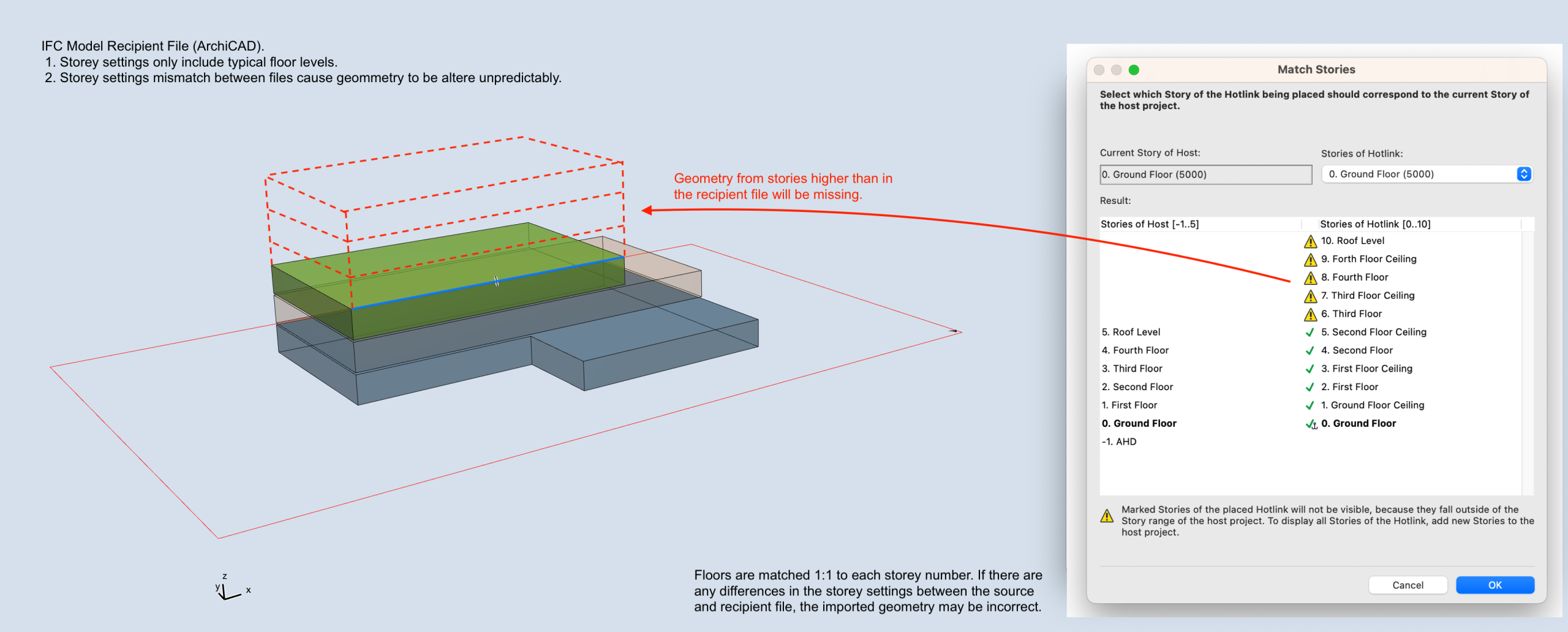
Different CAD platforms each manage and interpret storey levels in their own way. In ArchiCAD, it’s generally best practice to keep storey definitions straightforward, aligning them only with the primary building floors.
Revit, on the other hand, often incorporates additional reference levels, such as façade datums or ceiling benchmarks, which serve design and coordination purposes beyond actual storey definitions. When exchanged via IFC, these extra reference levels can be interpreted by ArchiCAD as true building storeys, sometimes causing elements to resize or reposition unexpectedly.

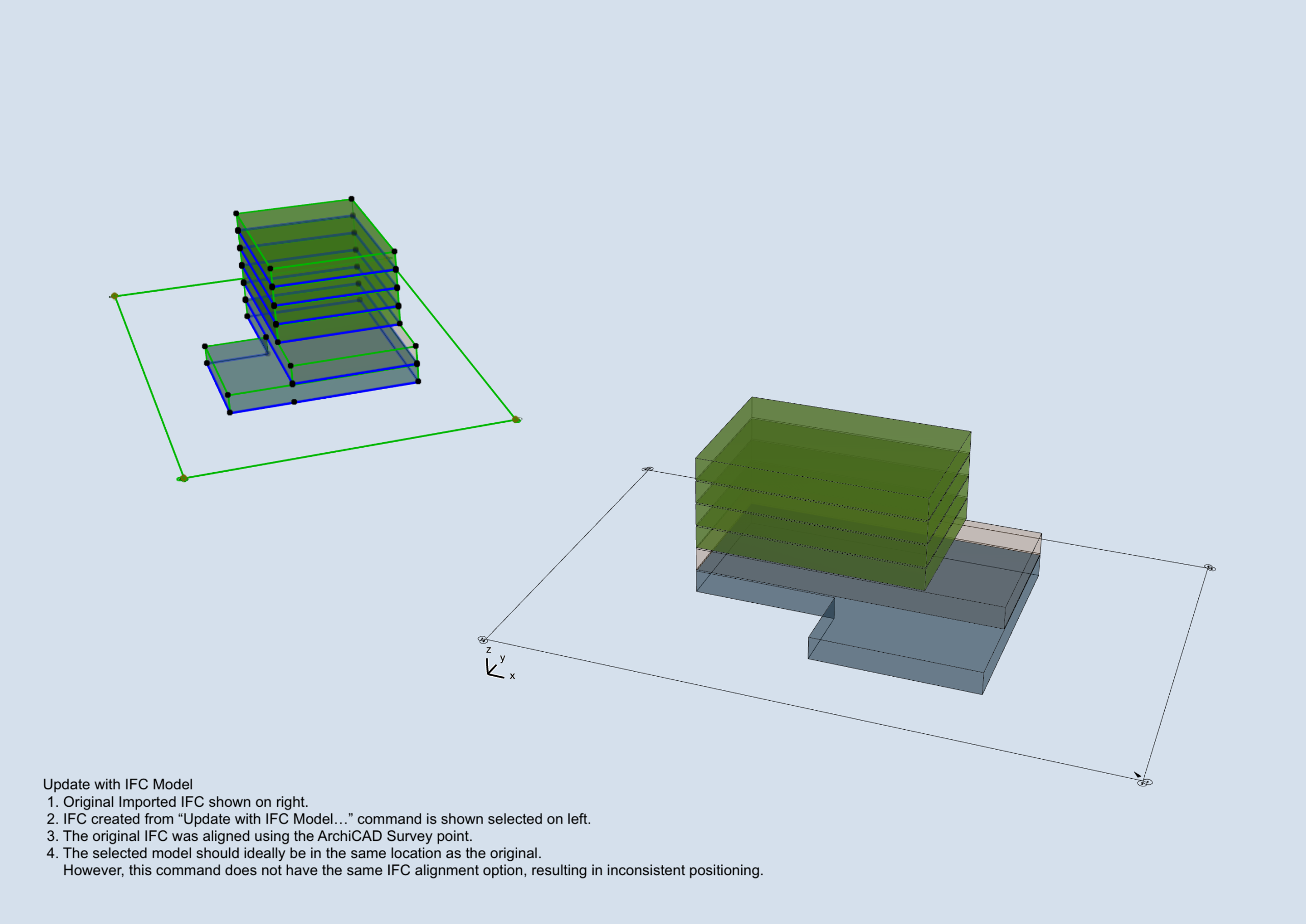
When importing IFC files into ArchiCAD, a commonly recommended approach is to reposition the model using survey points tied to world coordinates. This method works well and is included in our IFC Interoperability Guide here.
However, while effective for a single import, it introduces complications when ongoing coordination and repeated model updates are required. ArchiCAD’s “Update with IFC Model…” command is a powerful tool for both updating a referenced IFC and identifying revisions—information that IFC files typically do not communicate clearly.
The challenge is that this command does not account for survey-point-based repositioning. As a result, ArchiCAD may misplace the updated model, preventing accurate comparison with previous versions.
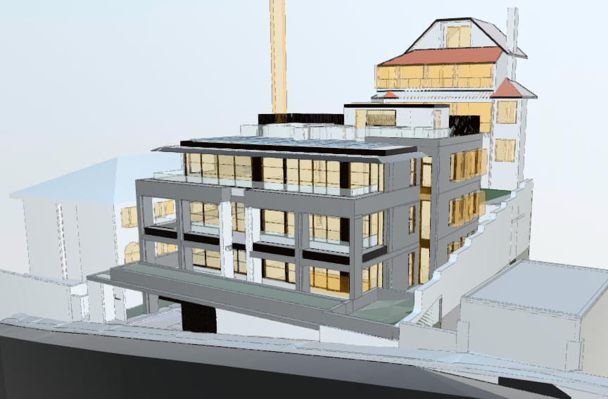
The way CAD platforms interpret and translate data from IFC files is often not the most transparent process. When a model is exchanged, the receiving application may display the data in unexpected ways, leading to various frustrations. Without access to additional software (often tied to a significant investment) it can be challenging to understand the full scope of how the model is being processed. In some cases, elements may be missing entirely, while others may appear with geometry that is generated inefficiently or inaccurately.
Below is an example of an IFC produced from ArchiCAD which had strange boundary boxes for services objects and openings. This was related to a specific setting in the IFC translator and not something that is obvious during a standard workflow.
Project Model Position
- Position model to the project origin as a the base point.
- Align the building’s main structures and grids with the screen’s orthogonal axis. View rotation should be set to 0°
- Set Project North according to the survey, taking into account the rotation from the previous step.
- In ArchiCAD: Project Preferences > Set Project North.
- To verify, toggle the survey point: Project Preferences > Survey Point > Show Survey Point.
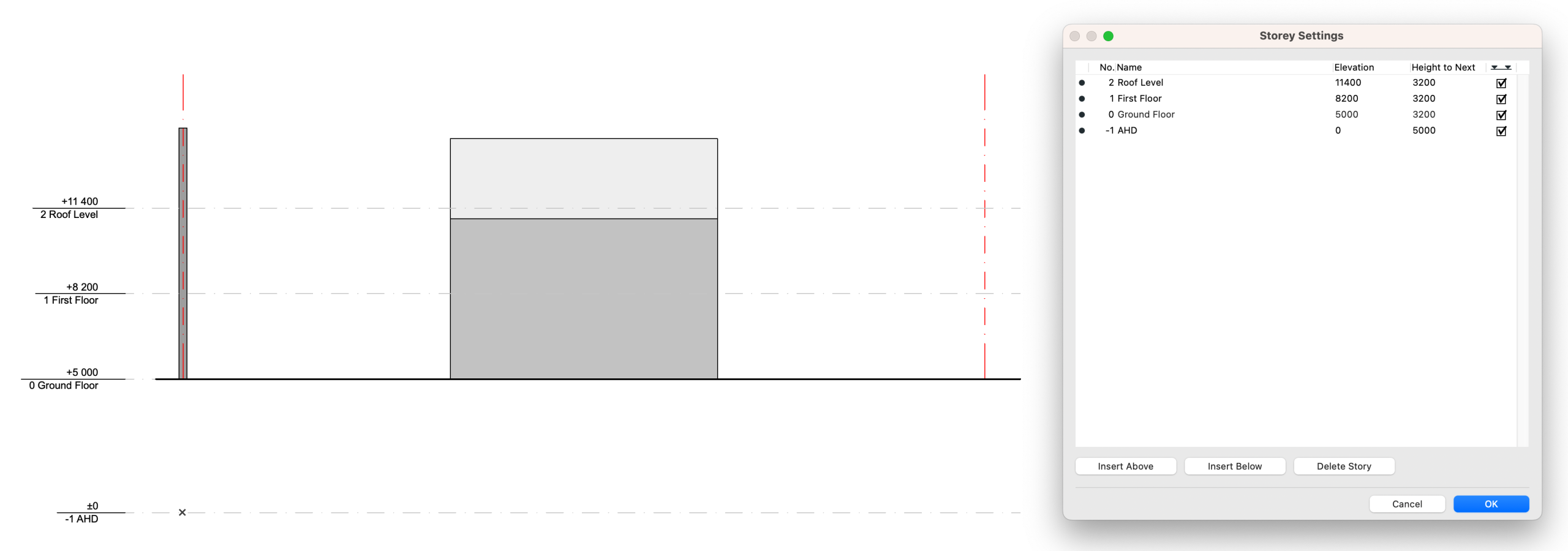
Storey Level Coordination
- Storey settings, including names and elevations, should be consistent across all parties.
- The project lead / architect is to establish a master table of storey levels to ensure correct vertical alignment.
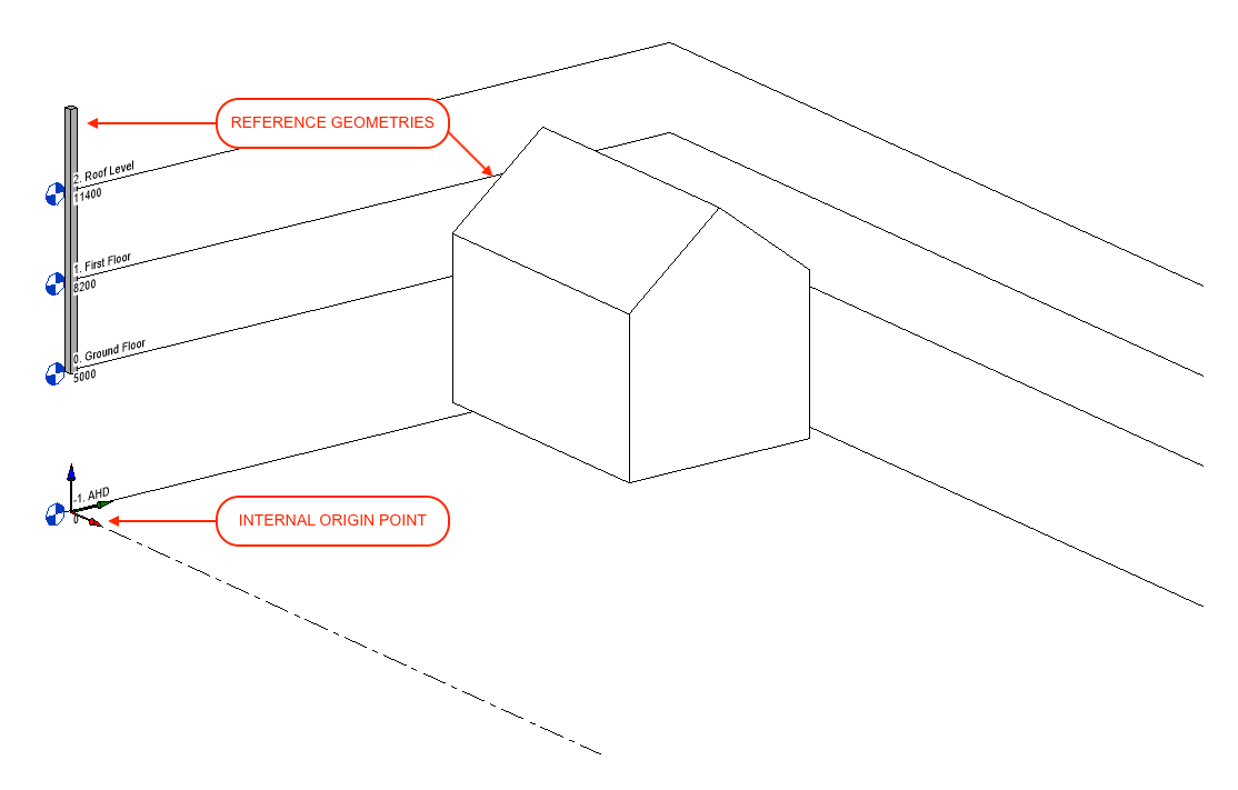
- Avoid modelling secondary reference levels as storeys (e.g. façade datum lines, ceiling, or sill levels).
- If there are any amendments to building levels during the duration of the project, updated values will need to be communicated to all parties.
- Note: Including a native multi-storey element in the IFC file will allow Revit to automatically generate relevant storey levels.
A column linked to the full height of the project is a useful way to avoid discrepancies between programs.
Coordination with Revit
- ArchiCAD’s project origin will be translated as an IFC project base point.
- Revit will then use this point to position the model against its own Internal Origin.
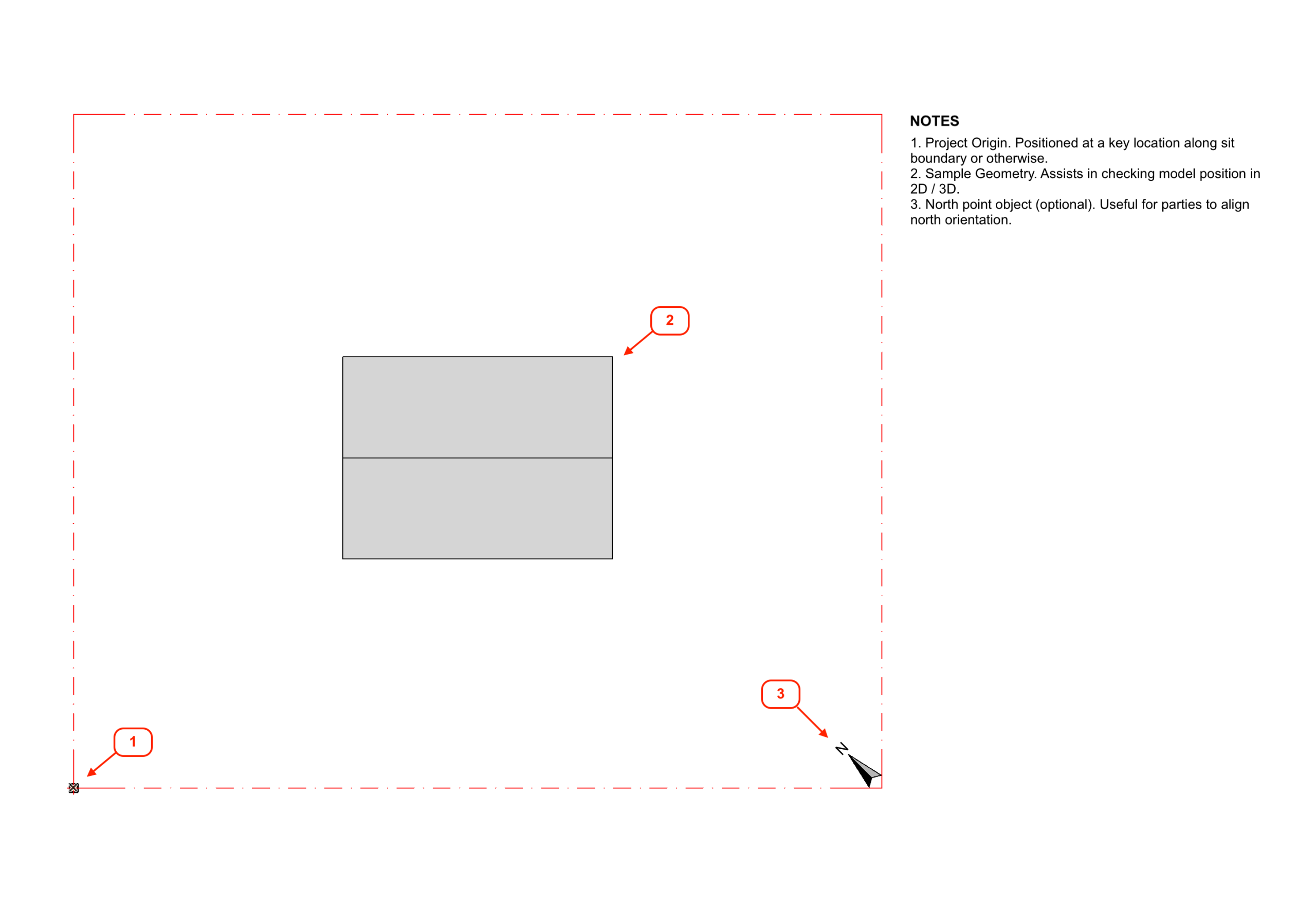
- This information should be circulated at the beginning of the project as a rudimentary IFC file. Include only essential details: Site Boundaries, Project Origin, and North Orientation.
- Draw coordination geometry:
- Site boundary as grid elements
- Multi-storey column linked to top storey
- 3D North marker
- Orient model to be orthogonal to screen
- Filter and setup saved 3D View
- Copy view into Publisher and set as IFC format.
- Set translator to “Smart IFC to Revit Export”.
- The translator will determine the model’s geometry, position and IFC properties/classifications.
- A copy of the translator can be extracted from our sample .pln file. Download here.
- A full breakdown of the settings can be viewed below.
- Publish and verify IFC contents by opening in a new ArchiCAD instance.

- Check model settings:
- North Orientation
- Project Orientation
- Storey Levels
- Go to File > Interoperability > Merge…
- Select File and click Open.
- Save library parts to external location. It is best avoid using the embedded library where possible.
- Select relevant elements in Merge Model Filter.
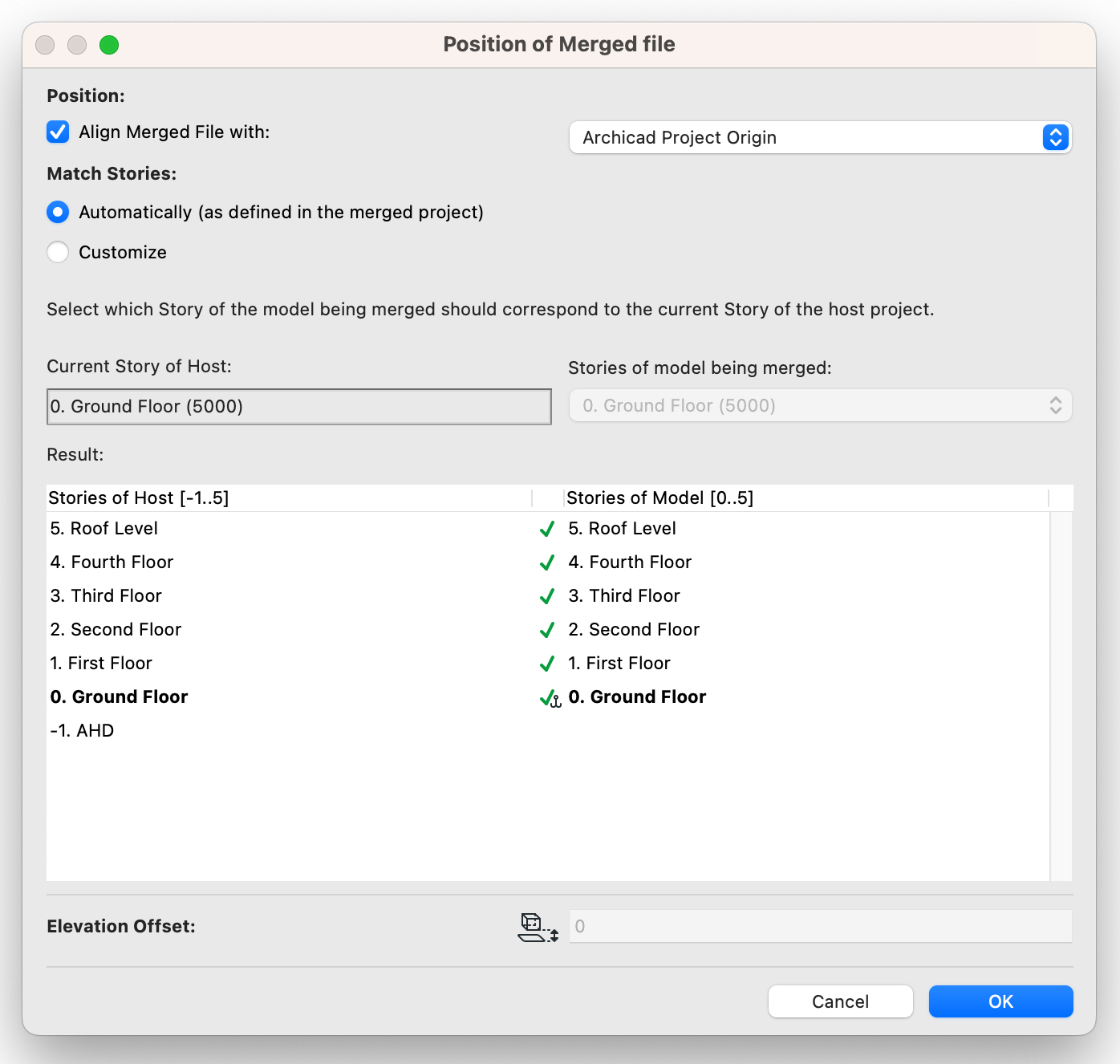
- Position IFC file.
- Position: Align Merged File with ArchiCAD Survey Point.
- Match Stories: Review resulting stories and ensure level match between IFC and host file. It is best to set the stories to match ‘Automatically’
- Enabling the ‘Customize’ setting allow for the model to be offset by a number of stories. This is often useful for niche uses, however it will not take into consideration the different heights of the stories and other factors. It is best to have the storey levels match exactly between all programs.
- Check Position of IFC Model.
Project Model Position
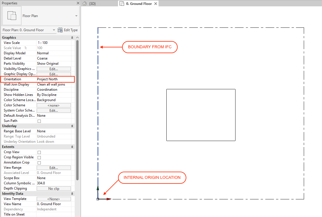
- The “Internal Origin” should be used as the base of coordination
- Set floor plan orientation view to “Project North”
- The project is to be oriented so that the building’s major structures/grids align with the screen’s orthogonal axis.
- Set project North
- This is done via Manage > Position > Rotate True North. (You will need to set the model orientation to ‘True North’ temporarily.)
- The north orientation is to be set according to the survey factoring in the rotation from the above step.
Storey Level Coordination
- Each storey and its associated name and elevation are to be consistent with ArchiCAD.
- The project lead should circulate a table of the project’s storey levels to be coordinated across all parties.
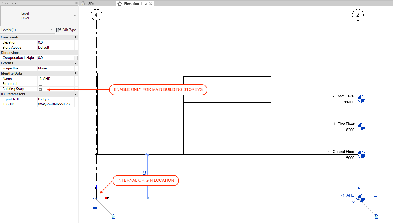
- Only major stories from the circulated table should be included as building stories.
- Any additional reference levels (facade datum lines, ceiling, sill levels etc) are to be amended so that it is not treated as a building story in their ‘Identity Data’.
Coordinate with ArchiCAD
- Revit’s Internal Origin point will be aligned against ArchiCAD’s Project Origin.
- The origin should be positioned at a key point on the site (i.e at a boundary corner) as determined by the Project Lead/Architect.
- Project Base Origin level will be set at AHD to match Internal Origin.
- Project Base Origin/ can be moved around provided the elevation does not change from 0.
- Prepare model for 3D IFC export.
- Ensure correct Visibility/Graphics Overrides for 3D View have correct settings.
- Open 3D view to verify.
- Load Smart Revit to ArchiCAD IFC.json file.
- This can be done via File > Export > IFC.
- The translator will determine the model’s geometry, position and IFC properties/classifications.
- A JSON file of the settings can be downloaded here.
- A full breakdown of the settings can be viewed below.

macinteract Pty. Ltd. | ABN 44 155 154 653 | terms and legal. | © 2026