
macinteract Pty. Ltd. | ABN 44 155 154 653 | terms and legal. | © 2026
Display settings for the various Drawing Tools, including:
Story Display
Floor Plan Display
Cut Fill Display
2D and 3D Display
Scale Dependant Detail
In the following section we will discuss how to control your Elements’ settings. We will distinguish between construction elements such (Wall, Column, Beam, Slab and Roof) and Openings (Doors, Windows, Empty Openings).
The respective Element Settings will have similarities. The general approach being that you have to:
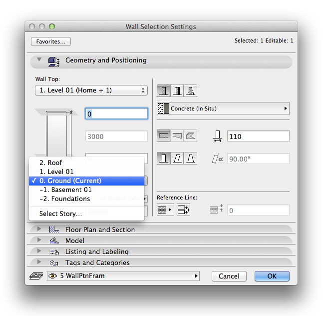
1. define a home story,
2. define a relation to stories (e.g. elevation to home story, linking element height to another story),
3. define if the element gets displayed on various stories or not and
4. define how it is displayed.
All these settings can be found in an element’s settings. Select relative element and Command+T.
The tabs of interest are:
1. Geometry and Positioning and
2. Floor Plan and Section
The biggest difference between construction elements and openings here is that construction elements relate to stories and openings relate to the construction element they are placed in. Therefore you cannot select a home story for a door or window.
The relation of construction elements to stories follows a logical procedure:
Home Story.
An element’s home story should be where its base resides, i.e. a column / wall’s home story would be where its base is even if it spans multiple stories upwards. Likewise a slab resides on the story where you’d put your feet on it. Where it gets more ambiguous is with beams, which by default are drawn as overhead elements.
INFO > By default the element’s home story is set to where it is drawn. If you happen to drag a drawn element in elevation, section or 3D to a different level the home story will not change automatically!
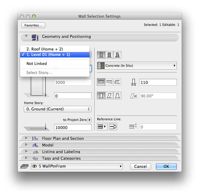
Not only can you set the elevation to the home story with positive or negative value for the dimension, for walls and columns you can also define if its height is linked to another story. If your story heights change, then with this setting walls and columns will automatically update to reflect those changes.
The big benefit of this in combination with Archicad’s Building Material priorities is that it would, for example, be possible to draw one continuous column that goes from ground to roof.
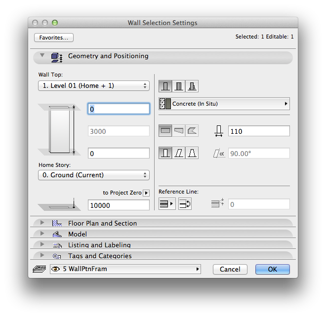
Where to find: Element Settings (Double Click the Toolbox icon for selected element or Command+T)>Floor Plan and Section
Use this to: Control how an element is displayed graphically on relevant stories.
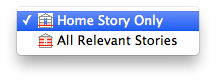
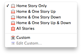
1. Show on Stories.
1.1 For Walls and Columns your options are according to the following image:
1.2 Slabs have additional options:
2. Floor Plan Display.
The options available depend on which Tool is currently active, but generally are as per the following image: Image 4
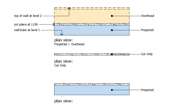
Typically walls are set to Cut Only, in other words walls or columns through which the default cut plane passes. The obvious exceptions are low height walls under 1150 in height, and thus these would use the Outlines Only display setting.
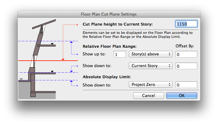
Note you can change the cut plane height in: Document>Floor Plan Cut Plane…
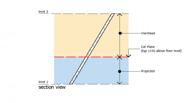
INFO > Projected will display the cut plane plus anything below the cut.
Projected with Overhead will display the cut plane as well as anything both below and above the cut.
This can be illustrated quite simply using a raked wall as an example:
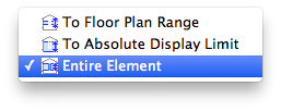
3. Show Projection.
In case you do select Projected as the Floor Plan Display option, you can further specify what is projected: Image 1
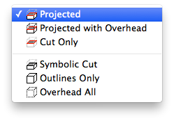
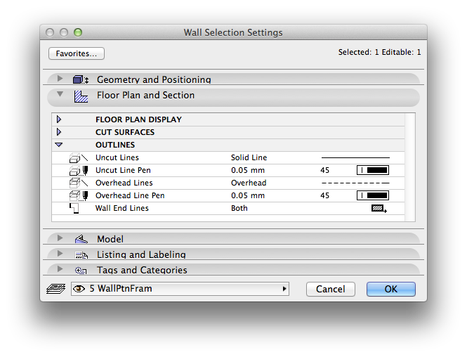
Note that you can define the overhead line type: Image 2
Special consideration must be given to Objects and Stairs as they have an extended set of options for you to control their behaviour. These additional options can be found in the Parameters tab.
macinteract Pty. Ltd. | ABN 44 155 154 653 | terms and legal. | © 2026
We use cookies to keep things running smoothly and help us improve—no secrets here!
Please select which cookies we can use. You can change your mind whenever you like!
Websites store cookies to enhance functionality and personalise your experience. You can manage your preferences, but blocking some cookies may impact site performance and services.
Essential cookies enable basic functions and are necessary for the proper function of the website.
These cookies are used for managing login functionality on this website.
Statistics cookies collect information anonymously. This information helps us understand how visitors use our website.
Google Analytics is a powerful tool that tracks and analyzes website traffic for informed marketing decisions.
Service URL: policies.google.com (opens in a new window)