
macinteract Pty. Ltd. | ABN 44 155 154 653 | terms and legal. | © 2025
1. You can place the Site Mesh on any relevant Story, however it is safer to assign the home story as per the paragraph “Add Stories”. That way you make sure the mesh doesn’t accidentally get elevated by adjusting story levels and you can easily perform a visual check to see if it is still sitting at the correct level. This also keeps the mesh off your plan drawings as it most likely will not adhere to your graphical standards.
2. Activate the Mesh tool by double clicking the relevant Favourite. If no Favourite has been set up open the Mesh settings and set one up. Set the Mesh Offset to a general level relevant to your survey and the Project Zero. Note Mesh Height defines the thickness of the mesh.
INFO > Keep in mind that the spot levels you add in the following steps relate to your Project Zero. Therefore the Mesh needs to be set up relating to the Project Zero as well.
3. Draw a mesh as a rectangle large enough for future perspectives and large enough for your sections and elevations. It is better to draw it too large than too small as adding to a mesh afterwards can be cumbersome.
4. Trace & Reference the survey.
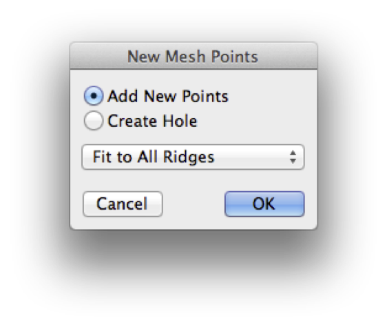
5. With the site mesh selected you can now add lines (sequential clicks) or points (double click the same spot). (Image 1)
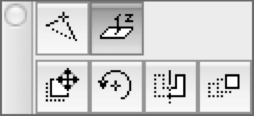
6. Add a Z-coordinate to either the entire line (your cursor will change to a tripod hovering over the line) or single points by clicking them and selecting the Z icon in the pet palette: (Image 2)
7. Enter the coordinate relative to the Project Zero: (Image 3)
With the area defined by the mesh and relevant information of the survey switched on you can now draw or, magic wand separate meshes for urban blocks: select the curb polyline+mesh>hold spacebar>click inside the boundary.
Repeat steps for existing structures. Remember to pick up parameters for correct mesh from the favourites.
TIP > With the site modelled in 3D you can make a copy of the mesh and elevate it to reflect height restrictions. Place this mesh on a layer that is typically turned off and adjust set it to a translucent material this gives clear indication in 3D where you are exceeding the height restriction. Next trace the mesh in sections or elevations as required.
Trace & Reference the survey worksheet and trace the boundary. Set up and use a boundary line-type as a favourite. Use the tracker for input.
Repeat above steps for setbacks.
TIP > For the setbacks, trace the boundary with a polyline (“P”) in offset mode (“U”). Use the tracker for numerical input.
Use Trace & Reference on sections and elevations to draw boundaries and setbacks in the correct location.
macinteract Pty. Ltd. | ABN 44 155 154 653 | terms and legal. | © 2025
We use cookies to keep things running smoothly and help us improve—no secrets here!
Please select which cookies we can use. You can change your mind whenever you like!
Websites store cookies to enhance functionality and personalise your experience. You can manage your preferences, but blocking some cookies may impact site performance and services.
Essential cookies enable basic functions and are necessary for the proper function of the website.
These cookies are used for managing login functionality on this website.
Statistics cookies collect information anonymously. This information helps us understand how visitors use our website.
Google Analytics is a powerful tool that tracks and analyzes website traffic for informed marketing decisions.
Service URL: policies.google.com