macinteract Pty. Ltd. | ABN 44 155 154 653 | terms and legal. | © 2026
The main principle in Archicad, as opposed to traditional 2D CAD packages, is the intent that all Architectural Drawings are generated directly from a 3D model. That means Elevations and Sections are by default directly linked to the 3d model and thus all changes made in either the 3D model or a linked Drawing are reflected live. With this approach one does not need to duplicate a 2D Floor Plan Drawing to generate a Reflected Ceiling Plan (RCP), instead one can simply change the display of various Elements and add more information into the 3D model.
To achieve this Archicad allows a high level of control over various aspects of Elements placed in a file, not only over the visibility of Elements but also to change their graphic representation properties as required.
There are various settings in various places, which can be categorised into Element level settings and Global Controls.
Display settings for the various Drawing Tools, including:
Story Display
Floor Plan Display
Cut Fill Display
2D and 3D Display
Scale Dependant Detail
In the following section we will discuss how to control your Elements’ settings. We will distinguish between construction elements such (Wall, Column, Beam, Slab and Roof) and Openings (Doors, Windows, Empty Openings).
The respective Element Settings will have similarities. The general approach being that you have to:
1. define a home story,
2. define a relation to stories (e.g. elevation to home story, linking element height to another story),
3. define if the element gets displayed on various stories or not and
4. define how it is displayed.
All these settings can be found in an element’s settings. Select relative element and Command+T.
The tabs of interest are:
1. Geometry and Positioning and
2. Floor Plan and Section
The biggest difference between construction elements and openings here is that construction elements relate to stories and openings relate to the construction element they are placed in. Therefore you cannot select a home story for a door or window.
The relation of construction elements to stories follows a logical procedure:
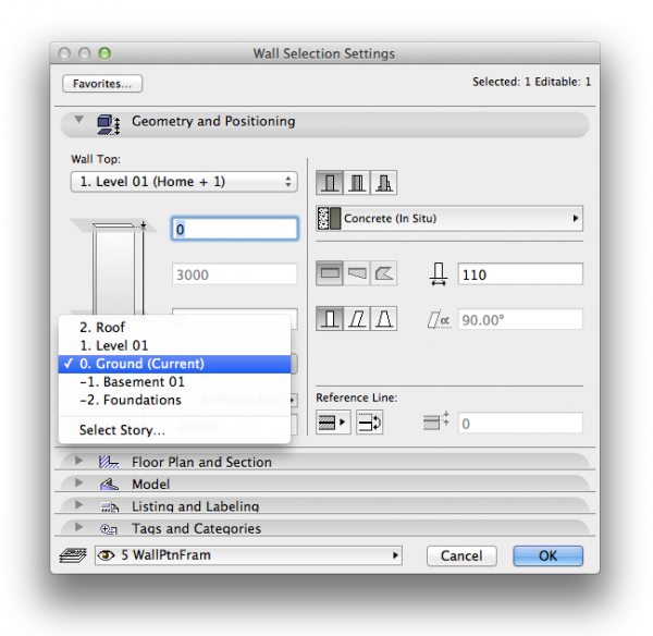
Home Story.
An element’s home story should be where its base resides,
i.e. a column / wall’s home story would be where its base is even if it spans multiple stories upwards. Likewise a slab resides on the story where you’d put your feet on it. Where it gets more ambiguous is with beams, which by default are drawn as overhead elements.
INFO > By default the element’s home story is set to where it is drawn. If you happen to drag a drawn element in elevation, section or 3D to a different level the home story will not change automatically!
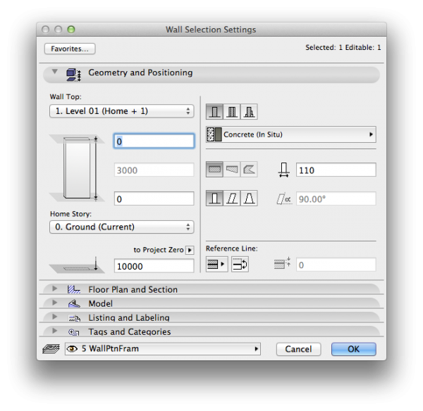
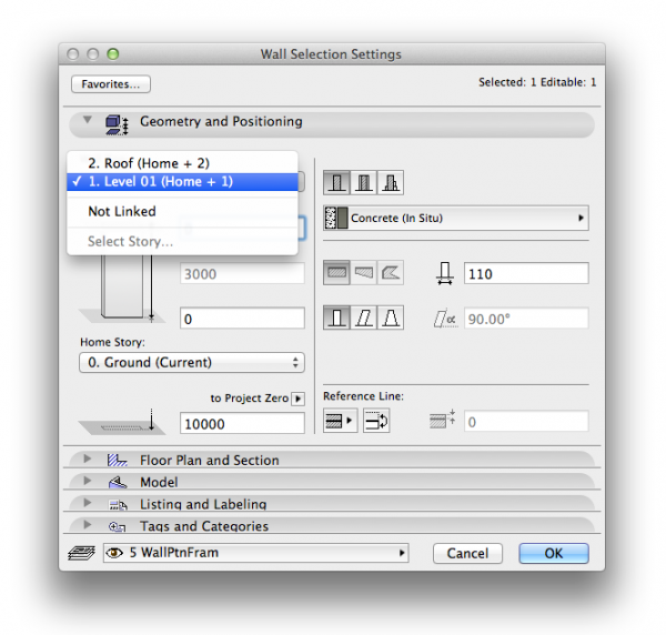
Relation to stories.
Not only can you set the elevation to the home story with positive or negative value for the dimension, for walls and columns you can also define if its height is linked to another story. If your story heights change, then with this setting walls and columns will automatically update to reflect those changes.
The big benefit of this in combination with Archicad’s Building Material priorities is that it would, for example, be possible to draw one continuous column that goes from ground to roof.
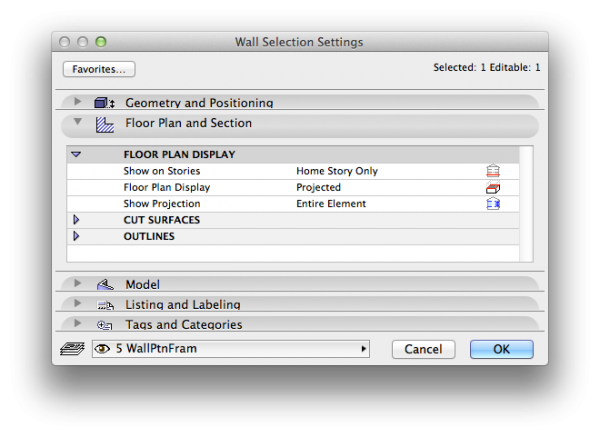
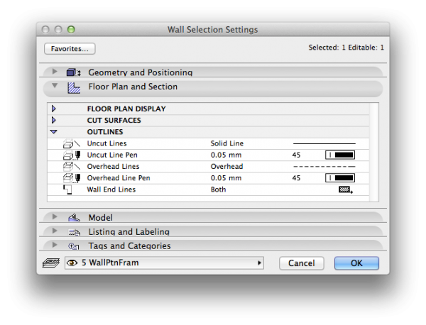
In the Floor Plan and Section tab is where you control how the element displays on relevant stories.
Floor Plan and Section.
Where to find:
Element Settings (Double Click the Toolbox icon for selected element or Command+T)>Floor Plan and Section
Use this to:
Control how an element is displayed graphically on relevant stories.
There are a number of display settings for walls, beams and columns in the floor plan view.
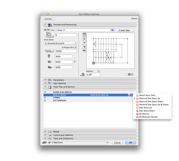
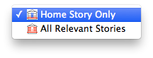
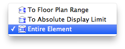
Show on Stories.
For Walls and Columns your options are according to the following image:
Typically walls and columns are set to Home Story Only. An exception can be Walls or Columns which due to their respective height may need to be visible on multiple stories.
Slabs and Beams have additional options:
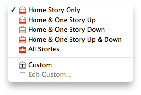
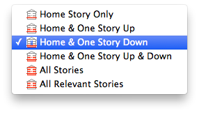
Floor Plan Display.
The options available depend on which Tool is currently active, but generally are as per the following image.
Typically walls are set to Cut Only, in other words walls or columns through which the default cut plane passes. The obvious exceptions are low height walls under 1150 in height, and thus these would use the Outlines Only display setting.
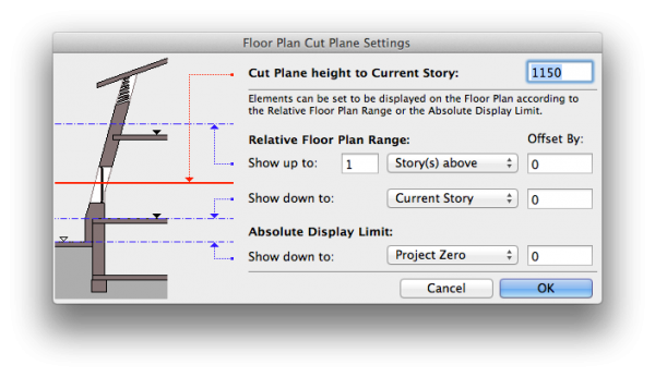
Note you can change the cut plane height in: Document>Floor Plan Cut Plane…
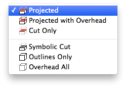
INFO > To display additional toolbars, select View > Tool Palettes > Large Tool Set.Projected will display the cut plane plus anything below the cut.
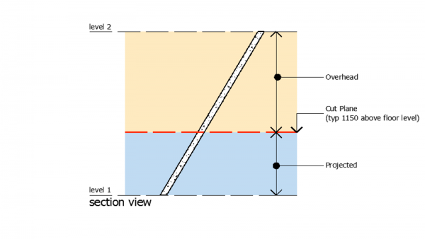
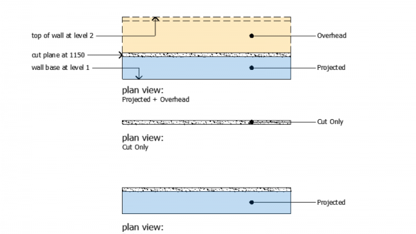
Projected with Overhead will display the cut plane as well as anything both below and above the cut.
This can be illustrated quite simply using a raked wall as an example:
In case you do select Projected as the Floor Plan Display option, you can further specify what is projected:
Note that you can define the overhead line type:
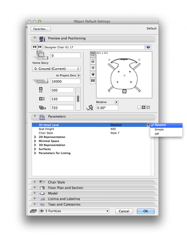
Special consideration must be given to Objects and Stairs as they have an extended set of options for you to control their behaviour. These additional options can be found in the Parameters tab.
Although there are many types of objects, with varying levels of dimensionality and complexity, here we will use an example of a common 3D object.
Most 3D objects have an option whereby the level of detail can be set, to either detailed 3D, Simple 3D or off altogether. It is recommended to set these to off wherever possible as 3D objects are typically memory intensive and may slow your file down.
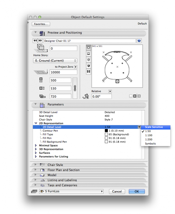
The level of 2D detail can also be set to either be automatically change when your view’s scale changes or you can pick one of the set scales so the object always displays the same no matter which scale your view is.
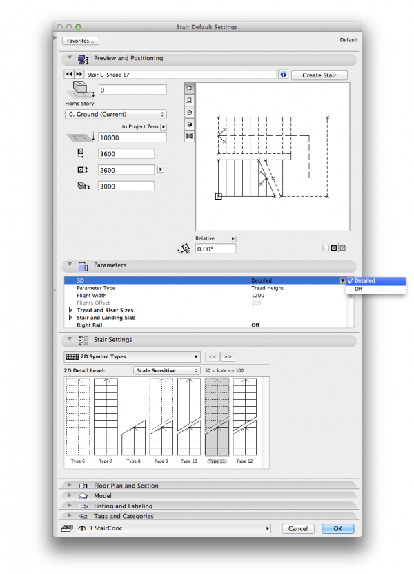
Without going into depth regarding how to create and/or draw stairs in Archicad, stairs have numerous Element Control settings for display for both 2D and 3D.
Level of Detail.
The level of detail can be adjusted depending on the scale of the relevant drawing as well as the amount of information that is displayed.
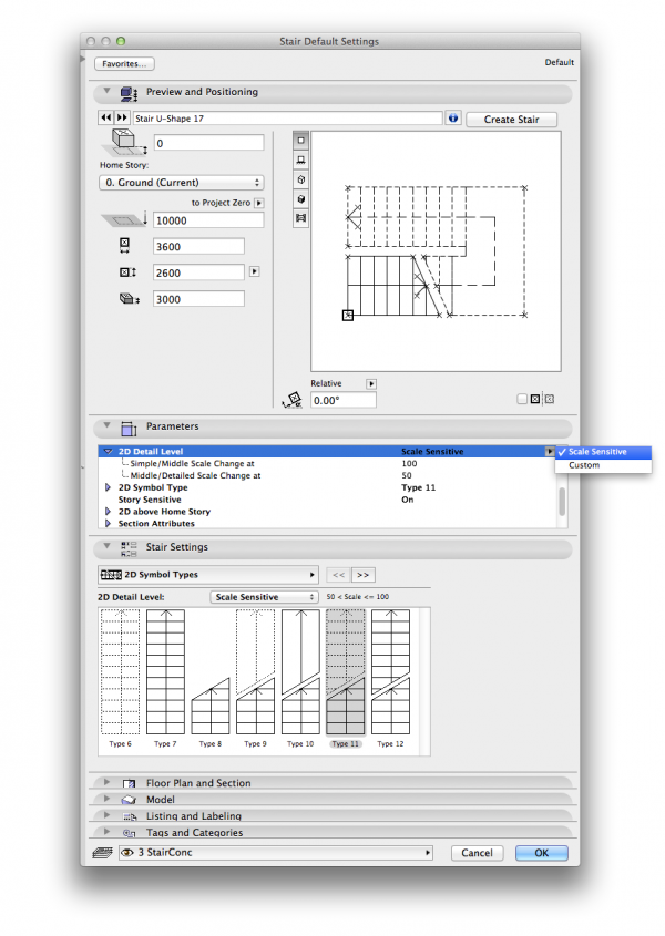
Story Sensitive.
A very important setting specific to stairs is the ability to be story sensitive. This means when the option is ticked the way a stair displays changes between home story and one story up. Without this setting enabled Stars will not display as intended. You can disable this option if your Stair does not run between stories, but only has a short run on its home story.
Relation to Stories.
Home story settings are set in the same manner as with other drawing tools.
Particular to stairs though, the most common display story setting is Home and Story up, since stairs typically span from one story to the next. This can, however, in combination with selecting a suitable 2D symbol type, be adjusted for stairs that travel only a short vertical distance.
In addition, stair displays include a break line, which indicates the following:
below break line = the flight up to the current story’s cut plane, and
above break line = the remainder of the stair above cut plane of the story below.
The lowest stair in a building would therefore only show its projected display, in other words only that part of the stair below the cut plane of that particular story. The topmost flight of any stair in a building would be set to display only that part of the stair above the cut plane projected from the story below. (Do not be tempted to place an additional stair on this level; check in section if uncertain.)
There are, of course, some situations where stairs placed in your drawing are somewhat tricky in terms of their display. For split level buildings, the cut plane will be set relative to either one or the other side of the “split”, so to speak. Check where the stairs sit in relation to this cut plane, and adjust their display settings accordingly. Should a stair in its entirety be placed below said cut plane, for example, the break line might possibly not be required. Check, however, where the stories below and above are placed in relation to this cut plane as it may also affect the display of stairs. A simple working section can aid with working this out.
macinteract Pty. Ltd. | ABN 44 155 154 653 | terms and legal. | © 2026
We use cookies to keep things running smoothly and help us improve—no secrets here!
Please select which cookies we can use. You can change your mind whenever you like!
Websites store cookies to enhance functionality and personalise your experience. You can manage your preferences, but blocking some cookies may impact site performance and services.
Essential cookies enable basic functions and are necessary for the proper function of the website.
These cookies are used for managing login functionality on this website.
Statistics cookies collect information anonymously. This information helps us understand how visitors use our website.
Google Analytics is a powerful tool that tracks and analyzes website traffic for informed marketing decisions.
Service URL: policies.google.com (opens in a new window)