
macinteract Pty. Ltd. | ABN 44 155 154 653 | terms and legal. | © 2026
In SketchUp you can generate accurate Shadow studies similar to any other professional CAD software. A geo-located model will cast real-world shadows as SketchUp will calculate these based on the exact model location using latitude and longitude, cardinal direction and timezone.
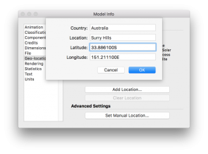
To geo-locate your model you can import terrain using the Add Location Tool (SketchUP PRO only) or add a location manually: select Window>Model Info>Geo-location>Set Manual Location and add latitude and longitude manually:
Add Location Tool
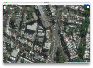
Select Add Location Tool or go File>Geo-location>Add Location, the Add Location window will pop-up. Type location address and press search, the map will display a satellite or street map of the desired location, choose Select Region and Grab a portion of the map.
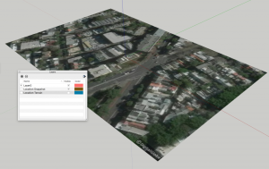
SketchUp will import the map on two Layers: Location Snapshot (flat image object) and Location Terrain (3D terrain model with mapped texture – hidden by default) and Geo-locate your model to World coordinates.
INFO > Map and terrain entities imported via the Add Location window are locked by default, to Unlock – select an entity, context-click and choose Unlock.
5 minutes 15 seconds
video by @SketchUp
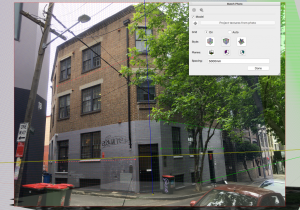
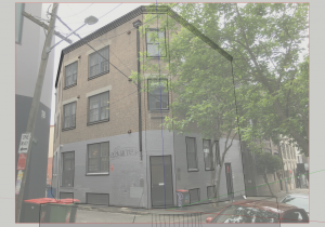
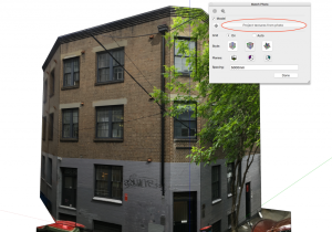
TIP > You can modify your Scene anytime. To access Match Photo mode select the mechanical wheel symbol in the Match Photo window or right-click on a respective scene and choose Edit Matched Photo.
INFO > Navigating through the model will guide you out of Match photo Scene and background image disappears. To get back to your Scene just simply click on Scene tab on top of the screen.
6 minutes 15 seconds
video by @SketchUp
video by @SketchUp
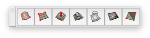
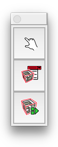
Use THESE tools to model terrain.
Where to find:
Tools > Sandbox
TIP > In SketchUp Pro, the Sandbox tools are enabled by default. In SketchUp Make, you also have access to the Sandbox tools, but you must enable them first. To enable the Sandbox tools, use the Extension Manager by selecting Window > Extension Manager.
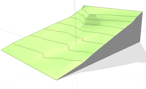
1. From Contours: Transform 3D contours into a site mesh
2. From Scratch: Create a terrain model from a flat site grid
3. Smoove: Sculpt your terrain -> Smooth and Move terrain in vertical direction
4. Stamp: Create a flat pad for placing an object onto terrain
5. Drape: Transfer edges from a flat surface onto terrain
6. Add Detail: Add more edges and faces to your site mesh
7. Flip Edge: Regularise the pattern of site mesh
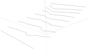
3D Contours > trace a survey or ask your Surveyor for a 3D CAD data file
Select entities and use The Sandbox Tool From Contours to build a site mesh
video by @SketchUp
video by @TutorialsUp
video by @SketchUp
video by @ SketchUp
video by @SketchUp
video by @SketchUp
m=Sketchup.active_model;v=m.shadow_info["SunDirection"];t=m.bounds.center;e=t.offset(v);m.active_view.camera.set(e,t,Z_AXIS,false);m.active_view.zoom_extents
video by @SketchUp
macinteract Pty. Ltd. | ABN 44 155 154 653 | terms and legal. | © 2026
We use cookies to keep things running smoothly and help us improve—no secrets here!
Please select which cookies we can use. You can change your mind whenever you like!
Websites store cookies to enhance functionality and personalise your experience. You can manage your preferences, but blocking some cookies may impact site performance and services.
Essential cookies enable basic functions and are necessary for the proper function of the website.
These cookies are used for managing login functionality on this website.
Statistics cookies collect information anonymously. This information helps us understand how visitors use our website.
Google Analytics is a powerful tool that tracks and analyzes website traffic for informed marketing decisions.
Service URL: policies.google.com (opens in a new window)