macinteract Pty. Ltd. | ABN 44 155 154 653 | terms and legal. | © 2026
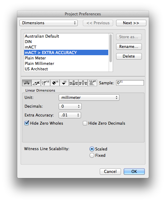
Where to find: Options>Project Preferences>Dimensions.
Options>Project Preferences>Calculation Units & Rules.
Use this to: Set up dimension accuracy schemes.
They will be part of your Saved Views and you can change current schemes via the Quick Options palette. Make sure to use “Store as…” after changing settings for linear, angular and other dimensions.
TIP > You can for example set up a scheme with very high accuracy (with 2 decimal places in Dimensions) for modelling vs. a standard accuracy scheme (no decimal places) to be used on printed drawings.
There are two ways to add dimensions:
Manual Dimensioning
Where to find: TOOLBOX, Dimension tab
Use this to: Manually select which nodes to include in your dimensioning.
Draw dimension lines:
1. Activate the tool via Favourites you have set up as part of your Office Standards.
2. Choose correct geometry method (G).
3. Click on relevant nodes (the element in question should light up to keep the dimension associated with that element)
4. Double click anywhere to finish selecting nodes
5. Use the tracker combined with snap function to place the dimension line.
Add nodes to existing dimension lines:
1. Select relevant dimension line.
2. Activate the tool by picking up parameters from existing line.
3. COMMAND + click nodes to be included.
Automatic dimensioning
Where to find: Document>Document Extras>Automatic Dimensioning>…
Use this to: Generate specified dimension lines by clicking on elements.
TIP > Draw a line or hotspot where you want to place the dimension line before starting to add dimensions or use the tracker (SHIFT + x or y) to enter coordinates.
Where to find: Toolbox, Dimension tab
Use this to: Add spot levels.
INFO > Beware of using spot levels linked to slabs as when the slab shape changes or if it is split the level marker jumps to a different location!
Reviewing the settings for the Level Dimension does not give you all available options.
After placing the dimension you can select its (placement) node, but also separately the text value. Selecting the latter and pressing Command + T will bring up options for the text where you can add prefix / postfix or other reference levels than project zero.
TIP > Turn on gravity (to roof, shell, slab or mesh) for the marker to pick up the top most element.
Archicad 17 has a dimension label accessible via the label settings described in the next paragraph. Using this label to place level dimensions binds it to the relevant element. I.e. If you move the element, the dimension moves with it. This also works for walls if for example you want to add a “top of wall” dimension.
Adding text is an essential part of annotating drawings and there are several ways of doing so, by means of the Text tool, Labels or Zone Stamps. The following paragraphs describe how and when to use which option.
Text
When to use: The Text tool, unlike Labels or Zone Stamps, places text that is not directly associated / linked to any element. It is important to realise the obvious: text can be placed anywhere, at any size and scale and can contain as much or as little wording as you wish.
Where to find: Toolbox: Text Tool
Open the Text settings window.
How to place Text:
There are two ways to place Text:
1. Draw a text box which will contain your annotation.
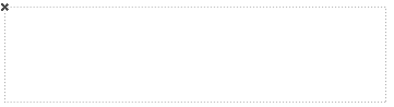
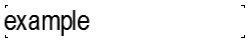
This method, however, is not recommended, as alignment of multiple text boxes is impossible. In addition your text is restricted to the size of the text box and should you need to add more text to your note at a later stage this can be problematic. (See Figure A and Figure B)
2. Double click on your workspace and type.
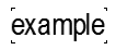
This is the recommended method as it allows you maximum control regarding placement, editing and alignment. (See Figure C)
TIP > Display Text-box Handles on screen in your drawing to aid with text alignment.
Go View > On Screen View Options > Text-box Handles.
INFO > Text placed in Hotlinks can not be edited anywhere else other than in the Hotlink source file.
Labels
Labels can be linked to an element as well as be independent. When used independently, the biggest advantage over using a normal text block is the option to display leaders / arrow heads. If linked to an element, labels can display properties of the linked element and will also keep their position relative to the linked element.
Where to find:
Toolbox: Label Tool
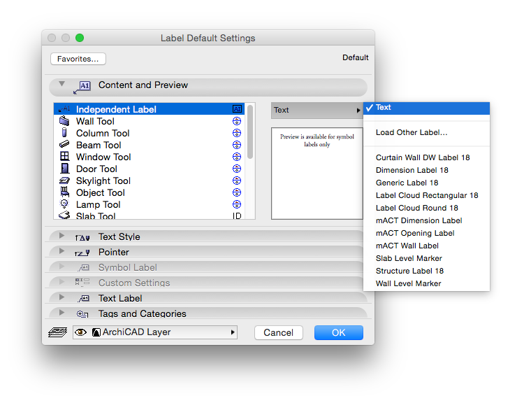
Open the Label settings window. There are different labels for different purposes and in the settings window you can define which label will be used for which element.
Workflow: There are two ways to place a label:
1. Placed manually via the label tool found in the Toolbox and thus not associated to an element. (Image 1)
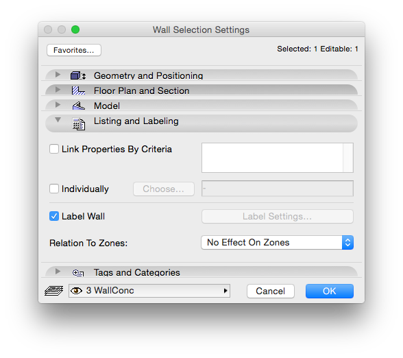
2. Tick the option to label a selected element in it’s Settings Window under Listing & Labelling. (Image 2)
Use this if you want the label associated to an element, i.e. it reads parameters from the element and keeps its place relative to the associated element.
INFO > Labels will most likely not be placed where you want them, so you will have to manually drag them to the right spot. Additionally when using labels with the arrow pointer, ensure the extension line node is further away than the length of the arrow head otherwise the arrow will invert itself.
There are various third party add-ons available that will let you manage labelling and listing of material attributes with varying degrees of success.
A tried and trusted method is to label manually:
Place associated Label and select it before opening its settings. Fill in and use either custom text or property fields, e.g. to show the material code.
macinteract Pty. Ltd. | ABN 44 155 154 653 | terms and legal. | © 2026
We use cookies to keep things running smoothly and help us improve—no secrets here!
Please select which cookies we can use. You can change your mind whenever you like!
Websites store cookies to enhance functionality and personalise your experience. You can manage your preferences, but blocking some cookies may impact site performance and services.
Essential cookies enable basic functions and are necessary for the proper function of the website.
These cookies are used for managing login functionality on this website.
Statistics cookies collect information anonymously. This information helps us understand how visitors use our website.
Google Analytics is a powerful tool that tracks and analyzes website traffic for informed marketing decisions.
Service URL: policies.google.com (opens in a new window)