B2-2
Modelling the Site
Introduction
One of the great advantages of modelling in 3D establishes itself in the ability to model the site in 3D with the Mesh tool. The site mesh will make an appearance in your sections and elevations, thus removing the necessity to deduct and draw levels in the traditional 2D drawing approach.
There are several ways to get site data modelled in Archicad.
Even if it is available to you, avoid importing 3D information as a gdl object into your project. The lack of editability and control over accuracy makes this quick solution a real problem. In addition, especially if your site is large and your survey detailed, do not include more detail than absolutely necessary.
This is for several reasons: It is time consuming, detailed meshes take longer to regenerate, and there is more chance of causing an error in the mesh (which might prove impossible to find and repair). Remember that while you do need to be accurate, the survey is also only an approximation of what is there on site. Therefore focus on the levels that are important for your drawings. If the site model captures an area larger than the project site, then you could also consider modelling to a greater level of detail (with a sufficient amount of spot levels) where it matters, and model less detail (using less spot levels) where possible.
Do not trace splines or lines from a consultant drawing with the Magic Wand. Tracing splines will (depending on your Magic Wand settings) add many more nodes than you need and will be more trouble than they are worth. Consultants’ drawings might not be drawn as accurately as required. Tracing their lines with the Magic Wand can be unpredictable and difficult to fix.
Importing the Survey
Archicad lets you do this in several ways.
For those who get 3D survey data in the form of a text or xyz file, go Design>Place Mesh from Surveyors Data…
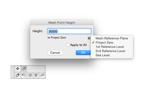
After pointing the dialogue window to the correct file you will need to fill in some properties in the following pop up window: (image)
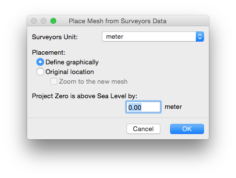
INFO > Choosing “Original” as the placement option might not place the mesh in the optimal location. Remember that Archicad stores coordinates relative to the project zero, i.e. large numbers in the coordinates take more processing power from your computer. Place the survey manually. We recommend placing the survey with an appropriate corner of the site boundary at the origin (0,0). Preferably this will be a physical point that can be utilised for site set out, such that it can also be related to project grids.
Also, surveyor’s units are limited to the options in the drop down menu as seen in the image above. Although this generally wouldn’t be a problem, you do have to check with the surveyor to which units the survey has been set, to accurately incorporate it into your Archicad project. (Scaling the mesh is possible via COMMAND + K, however you would want to avoid becoming liable for these kind of edits that you make.)
If you only have a 2D drawing from your surveyor then follow these steps:
1. Create a new Worksheet by activating the Worksheet Tool in the Tool Box. Ensure it is assigned to a dedicated Layer that does not show on any drawings to be printed. The size of the drawn frame does not matter. Give this worksheet a logical name so you can easily find it in the list, e.g. ConsultantCode_Survey.
Note that while you can create independent worksheets, they sometimes don’t behave as dependably as one might expect in terms of positioning them correctly as a trace & reference.
2. Open the worksheet by double clicking it in the Project View Map.
3. With the worksheet open go File > External Content > Place External Drawing.
INFO > Do not import a DWG as an XREF. Instead place an external drawing to avoid bringing in layers and other file polluting attributes!
4. Place and rotate the external drawing in a logical location, i.e. a corner of your site on project zero. Rotate so it fits on your layout (portrait or landscape). You can adjust the Project North so it matches the rotated survey far more easily than rotating every drawing on every layout.
5. Lock the External Drawing – EDIT>Locking>Lock
6. With the survey placed correctly go back to the Floor Plan view / 2D window.
Select the survey worksheet in the Project Map, Right Click it > Show as Trace Reference. In the Trace & Reference palette make sure it sits on top 7. of your drawing and preferably has a single easily identifiable colour. You can also adjust the opacity as required.
Draw the Mesh
1. Make sure you are on the correct story.
TIP > Typically, levels on Surveyors’ drawings are relative to a Height Datum, for example, sea level. If you work off a dedicated 0 height datum storey as a reference, consider putting the Mesh base at that level, which will allow you to simply type in the spot or contour levels exactly as they appear on the survey. This also provides an easy visual check that the Mesh is positioned correctly.
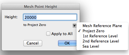
2. Activate the Mesh Tool and check its settings to ensure that the Mesh Height reflects a base RL, e.g. the lowest level on site, from which you can start adding higher levels. How deep the Mesh is depends on your preferences of how the Mesh displays in Sections and Elevations.
INFO > Keep in mind that the spot levels you add in the following steps relate to your Project Zero. Therefore the Mesh needs to be set up relating to the Project Zero as well.
3. Draw a rectangle for the Mesh.
Consider the size of this rectangle well; you would want to catch at least the site with some relevant immediate surroundings. How much do you want to appear in sections / elevations / perspectives?
INFO > Modifying a mesh at a later date can be a lengthy and time consuming process, so it is best to add as much data as possible at creation.
Adding the necessary levels
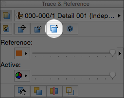
1. Make sure your Trace & Reference is on, in the correct location as well as rotated correctly. Note you can reset the Trace & Reference to its default position vie the below button.
2. Select the Mesh (!) and activate the Mesh Tool.
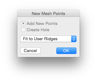
3. Now you can either add spot levels by double clicking a point on the Mesh or you can draw a polyline connecting equal RL’s (in other words, a contour). The latter means less work as you can lift the entire contour line to the designated RL in one go, instead of lifting every single node to the RL individually, by simply clicking a line segment (the cursor will change to a tripod) and ticking Apply to All.
INFO > Ensure that ‘contour’ line polylines (i.e. not splines) extend beyond the edges of your mesh, or the mesh profile will be distorted at the perimeter of your model
INFO > When using Apply to All, you will need to check nodes that intersect with the edge of the mesh, to verify that they adopted the correct level coordinates. Use the Z tab (Elevate Mesh Point…) in the tracker to adjust these nodes if required.
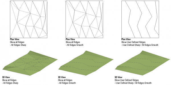
INFO > You can control how the Mesh displays to suit your needs:
Smooth vs Sharp Ridges
All Ridges visible vs User Defined visible
These effects are illustrated in the images to the right:
Show User Defined Ridges & Show all Ridges affect the plan view only.
All Ridges Sharp & User Defined Sharp affect the 3D view only. (All Ridges Smooth seemingly has little visible effect on the 3D view.)
AC-B32 Alternative display options of Meshes < INFO
With the site and immediate context now defined by the mesh, and relevant survey information switched on, you can now draw separate meshes for urban blocks, roads etc. Ensure that these various meshes connect perfectly in plan in order to avoid meshes displaying with gaps between them in sections and elevations.
Repeat steps for existing structures if applicable. Remember to pick up parameters for correct mesh settings from any preset favourites.
TIP > With the site modelled in 3D you can make a copy of the mesh and elevate it to reflect height restrictions. Place this mesh on a layer that is typically turned off and adjust set it to a translucent material this gives a clear indication in 3D where you are exceeding the height restriction. Next trace the mesh in sections or elevations as required.
Tips & Good Practice
Often the site levels will need to be modified to fit the design. Keep a copy of the original site mesh on a dedicated layer that is typically locked and switched off. Doing this has various benefits:
You have a copy to fall back on in case something goes wrong with the proposed site mesh.
With its layer switched on, you can trace the existing ground line with a polyline in sections if required to do so.
Ability to compare net volumes via the setup of a schedule in order to calculate the amount of excavation or fill.
Use the element ID to identify each mesh is what, e.g. TerrainProposed or TerrainExisting.
Besides modifying the spot levels you can use Solid Element Operations (Subtraction with Upwards Extrusion) on the lowest parts of the structure (Foundations, Slabs,…) to deduct that volume from the site mesh. A mesh cannot have two spot levels occupying the same x,y coordinates. This means that a sharp vertical level change, used to represent, say, a building block or a kerb edge, is impossible to model using just one mesh. Model these items as separate meshes where sharp vertical edges are required.
In early design stages such as Feasibility and Design Development, a quick method of modelling site context such as roads, is to model the entire locale with one mesh as defined by the survey, then duplicate this mesh and move one off to the side (to a fixed distance, e.g.. 100m). On one mesh cut the roads out as holes, and on the second, trim away the site leaving just the roads. Select a different Surface Override for each mesh if needed. Move the second mesh back to the original location, where the two should now meet perfectly. Select the road mesh (not the site mesh as you need accurate level there!) and elevate down by the height of the kerb (typically -150mm) and you will have kerbs displaying in 3D, Elevation and Section.
macinteract Pty. Ltd. | ABN 44 155 154 653 | terms and legal. | © 2026