B2-1
Importing Consultants Drawings
Introduction
In order to coordinate your Architectural drawings with those of other Consultants (Structural, Mechanical, Hydraulic, etc), one needs to place the External drawings (CAD files or PDFs) from the various consultants in your Archicad file to use as a reference, whilst ensuring that no attributes from these drawings pollute your file.
2D CAD files (DWG, DXF, etc.) should always be imported as Drawings and NEVER as an Xref!
This prevents your Archicad files becoming polluted with unwanted attributes. Place them as external drawings in relation to the project / project origin and at the correct scale.
INFO > You can still snap to elements in these drawings as well as control their layer display via the Drawing Settings dialogue!
CAUTION > The following options relate to using external drawings as a reference. If you need to incorporate the drawn information into your model, your first option should be to trace / draw it with the external drawing as your reference. Although it might seem a lot of work at the time, having to clean up polluted attributes and drawing inaccuracies from the external drawing is a much more time consuming and frustrating job!
Besides this, if you are liable for what is represented on your drawings, having to draw instead of copy/paste information forces you to scrutinise the external drawing(s).
TIP > If you must use the linework from a consultant file, consider importing this external drawing into a separate blank file created from your Standard Template first to clean up the data and reapply the correct preferences. It is easy to see and delete foreign attributes in this file, before migrating the data into your project file, and risk contaminating your Project.
Workflow
There are two approaches to Importing External Drawings:
1. Placement on Worksheets. (Preferred Method)
Use this if the relevant drawing needs to be referenced on various stories, elevations, sections, etc. This is particularly true of a project survey which typically will be referenced into the project at it’s inception.
This avoids needing extra layers to turn on/off their visibility as described below in approach 2. An added benefit is that you can trace and reference these worksheets where needed, giving a clear distinction between what’s yours to edit and what is not, by adjusting the opacity and / or colours in the Trace & Reference palette. In Project Map, create a new Worksheet for each Consultant and name accordingly.
Open the relevant worksheet, and Go File>External Content>Place External Drawing. Select the DWG or DXF file for the relevant discipline from your Project Server. Place the External Drawing in relation to the project / project origin and at the correct scale. Lock the external drawing in place (Not just the layer) Edit>Locking>Lock to avoid it being accidentally moved. Return to your workspace and use Trace & Reference to view placed drawing.
Repeat these steps for each consultant.
2. Placement on relevant Story, Elevation or Section.
Use this if only needed as a reference in one place.
Should you choose this option, you will need to place the external drawing on an easily identifiable external drawing Master Layer, e.g. ExternalDrawing_Hydraulic (or similar). You can also add the extension “IMP” for import to the layer which makes it easier to organise and filter your layer list. Also lock the layer to avoid accidental edits.
To clearly identify the reference from your model you can set up pen sets dedicated to the various disciplines, which you can set to override the original pen set in the External Drawing’s settings window. In these dedicated pen sets, unify the colours to a single clearly distinguishable colour to mimic the Trace & Reference behaviour, with the exception of pen #91, which is always set to white
Go File>External Content>Place External Drawing. Select the DWG file for the relevant discipline from your Project Server.
Place the External Drawing in relation to the project / project origin and at the correct scale.
Place on a designated Layer (eg. Consultant Import_Structure).
Select the External Drawing and open its properties.
Select and apply the Pen Set that you created for the particular Consultant.
Repeat these steps for each consultant using a different colour pen set for each.
INFO > Method 2 is particularly useful for consultant coordination and clash detection of services, as you are able to view multiple consultants’ drawings as well as your own simultaneously by merely toggling on/off the relevant layers.
Ensure you update external drawings whenever new information is received from your consultants to ensure that only the most recent information is in your file.
In addition, avoid keeping superseded consultant DWG’s in your file as this impacts both your file size as well as, eventually, your speed.
TIP > In order that this be done effectively – a dedicated location on your server for Current consultant data is worthwhile on a per project basis so that everyone is aware of the location for referenced files.
If a consistent file name is used for the consultant drawing (Without a Revision/version Number), the file can be swapped out with a current version (with the same name) and Archicad will recognise that the file has changed and alert you so that it can be manually updated from within your project.
CAUTION > Warning: If you relink the file to a new instance (instead of this method) – the files origin relative to your project may have moved or been modified and you will have to place again from scratch.
INFO > You can still snap to elements in these drawings as well as control their layer display via the Drawing Settings dialogue!
CAUTION > The following options relate to using external drawings as a reference. If you need to incorporate the drawn information into your model, your first option should be to trace / draw it with the external drawing as your reference. Although it might seem a lot of work at the time, having to clean up polluted attributes and drawing inaccuracies from the external drawing is a much more time consuming and frustrating job!
Besides this, if you are liable for what is represented on your drawings, having to draw instead of copy/paste information forces you to scrutinise the external drawing(s).
TIP > If you must use the linework from a consultant file, consider importing this external drawing into a separate blank file created from your Standard Template first to clean up the data and reapply the correct preferences. It is easy to see and delete foreign attributes in this file, before migrating the data into your project file, and risk contaminating your Project.
Drawing Control
You are able to control visible layers in placed DWG files, and once again there are two means of doing this.
1. Should you know the layer structure of the drawing,
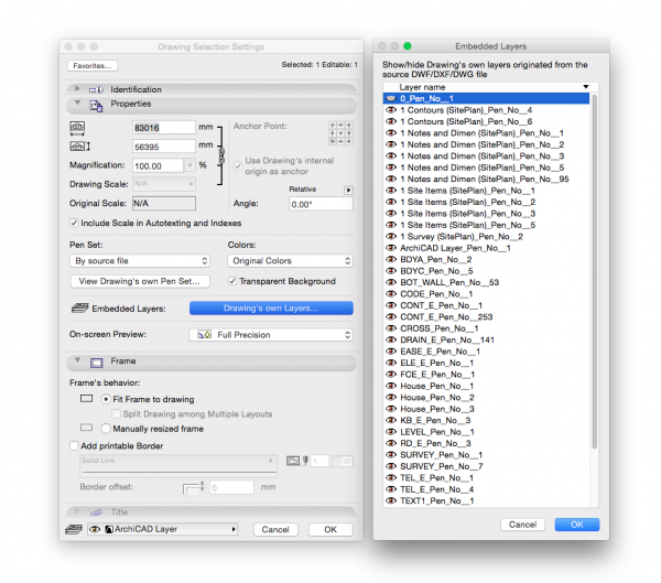
select the drawing and open its Settings (COMMAND + T).
Go Embedded layers>Drawing’s Own Layers… and the full list of layers contained in the file will be available.
Toggle off those you do not require.
2. Right click on an unwanted element visible in the DWG, and go “Hide Embedded Layer”. This will hide all elements drawn in that layer. Repeat as required.
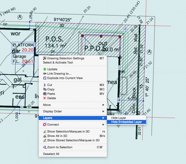
INFO > Should you accidentally hide a layer in the placed drawing that you actually wish to display, you may have to turn all the layers back on again (using method 1) and begin again, as unfortunately method 2 does not display what the names of the embedded layers are from within that Context menu.
CAUTION > Having DWGs in your file can make Archicad less responsive, typically when opening or saving a project. It is best to be in control of what updates when, thus the placed DWG’s should be set to update manually. The method below describes this process (the long way via the Drawing Manager), since it is the only way to review all placed drawings simultaneously. There is always the option, however, following steps 3 – 6 on individual drawings selected in your view (plan, section, elevation…).
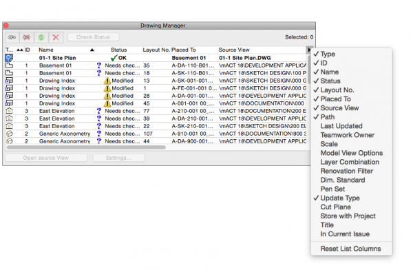
1. Open the Drawing Manager via File > External Content > Drawing Manager.
2. Optional:If not already present, add the Update Type column via the black triangle icon in the top right. Click the column header to organise the list by Update Type to quickly check which drawings are set to Auto or Manual Update.
4. Open the Drawing Selection Settings via the Settings… button.
5. Set Update Type : Manual.
6. Click OK. < CAUTION
macinteract Pty. Ltd. | ABN 44 155 154 653 | terms and legal. | © 2026