B5-3
Global Controls
These controls are able to override the Element Control Settings and are listed in the View Settings Dialog Box:
View Settings.
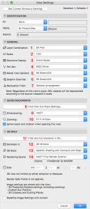
View Settings are used in the View Map, the settings are divided into four categories;
A. Identification
B. General
C. 2D/3D Documents
D. 3D Only
Details for each section as Annotated in the dialogue box shown above can be found below:
1. Layers & Layer Combinations.
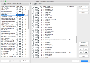
Layer Combinations are sets of Layer settings defining which Layers are visible or hidden, unlocked or locked and the layer intersection priority index for a specific Layer Combination. By turning different combinations of layers on of off, the output is set. For example, a certain layer combination will be used for a General Arrangement Drawing, whilst a different one will be used for a Concrete Profile or RCP. Saved views contain, amongst other settings, a particular layer combination.
Layer Combinations are listed on the left panel of the Layer Settings Dialog Box; individual Layers are listed on the right.
Archicad and the Smart Template come with pre-defined Layer combinations covering every design phase and viewpoint.
INFO > Beware of “Custom” layer combinations in your saved views, as this will result in inconsistent displays of your drawings for output.
Correct and consistent use of Layers is critical to any file structure. In addition, Layers have a Priority Number, which determines the Intersection Priority of Construction Elements. This is particularly important for the junctions of Walls and other Structural Elements such as Concrete Slabs, Beams and Thickenings. Only elements on equal priority numbered layers will connect.
INFO > Layer Priorities override the Intersection Priorities set in Building Materials, as well as Model View Options.
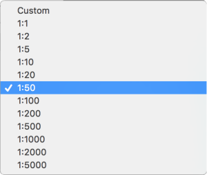
2. Scale
Scale of the View.
Model Size elements or the 2D Symbol of some GDL Objects can be set to be sensitive to the current scale: the symbol may vary depending on the current scale.
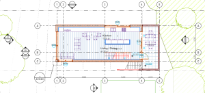
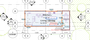
Good practice is to save each View in the same scale as it will be published as you can exactly see how the drawing elements will overlap/align while working in plan (see 2 views of the Smart Template Example Project below for 1:100 and 1:200 Scale):
3. Structure Display
The Structure Display function allows you to display construction elements in various ways depending on their structural type.
This can be handy if you want to for example display only Load-Bearing elements for Structural Setout Plans.
Options to choose from are…
1. Entire Model
2. Without Finishes
3. Core Only
4. Core of Load-Bearing Elements Only
…and are used to control the display of composites for use in different drawing types. For example, should a number of your structural walls be drawn using composites, showing say, concrete with a lining of some sort, this lining will show up on your concrete profile drawings unless you select a different display, as Entire Model is the default setting.

INFO > Be careful when selecting Structure Display, for use with Concrete Profiles. For example, should you wish to set your Structure Display to “Core Only” so that the finishes of wall composites are not visible, ensure that this is set before you start dimensioning, otherwise dimensions may not be displayed.
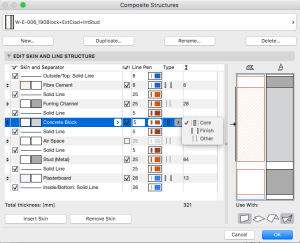
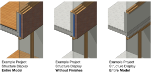
For composite elements (Wall, Slab, Roof, Shell): skins can be defined as either Core, Finish, or Other in the Composite Structures Dialog Box.
4. Pen Set
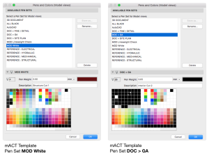
Set of Pens & Colours that can be assigned to any element of the Virtual Building Model to control the pen colour and weight, e.g. to adjust the pen weight for differently scaled drawings.There are 255 pens available in the table. Their index numbers are indicated by their position in the table. Each Pen Set assigns different parameters (pen colour, pen thickness, description) to the same pen index number.
Archicad and the Smart Template come with several predefined Pen Sets (Options > Element Attributes > Pens & Colors)
Pen sets can be specifically set up to override standard drawing displays:
Scale.
Scaled drawings can be problematic. Consider the implications of reducing a drawing from say 1:20 to 1:200 without changing the pen set to one with finer line weights and better tuned to your printer. The drawing will be very hard to read as the thick pen weights will mask much of the detail. Create Pen Sets for the most commonly used scales and ensure that these are saved into your office template for use across all projects. Select the appropriate pen set to ensure clear output for various drawing types.
Printing.
Different printers are only able to print certain line weights. Set up specific pen sets for your designated office printer(s) and name accordingly e.g. 1:100_Bold, or 1:100_Fine. Once again save these pen sets into your office template, and ensure the correct pen set is used for whichever printer you are using.
Highlighting.
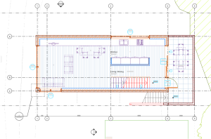
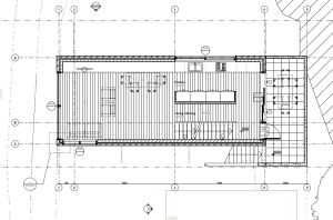
To clearly identify certain element groups in your model, you can set up pen sets dedicated to specific disciplines such as consultants’ drawings. Unify the colours to a single clearly distinguishable colour e.g. Structure = all red; Mechanical = all blue etc. In the External Drawing’s settings window you can set to override the original pen set.This is particularly useful during the consultant coordination process.
Specific Drawing Types.
To create specific Drawings, such as Fire Resistance Level Plans pen sets can also be used to override the Background Fill colour of Walls – please refer to the How-To Guide for detailed instructions.
5. Model View Options
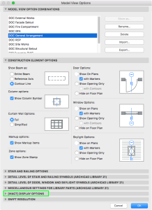
The display and output of Model View elements can be set and overridden globally in Document > Model View > Model View Options.
Model View Options affect the on-screen and output display of construction elements and certain Library objects throughout the project (globally).
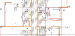
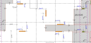
Options include control of graphic display, cut and cover fill types and overrides, object specific toggles, e.g. to quickly override all wall cut fills to black for a Presentation Drawing or to hide all Door and Window objects for a Concrete Profile Drawing.
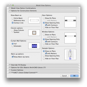
Model View Options dialog box is divided into separate panels where you can globally override element settings:
Options for Construction Elements.
Example: you can switch to a Reflected Ceiling Plan by switching of Doors & Windows globally here.
• beams
• columns
• curtain walls
• doors & windows
• skylights
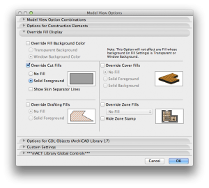
Override Fill Display.
INFO > To display additional toolbars, select View > Tool Palettes > Large Tool Set.
Example: set cut fills to solid foreground for design stages rather than showing detailed construction type fills.
• Background Fills
• Drafting Fills
• Cover Fills
• Zone Fills
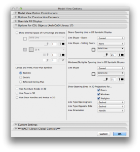
Options for GDL Objects.
This section can tap into relevant objects to change the way they display globally. With solid knowledge of scripting it is possible to program custom setting to control globally.
• Minimal Space
• Lamps
• Hide Elements
• Opening Lines
Custom Settings.
GDL Macros can be scripted to enable specific MVO’s tap into your (custom made) objects.
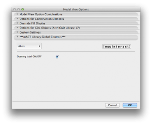
Smart Template Library comes with additional panel [Smart Template] DISPLAY OPTIONS from where you can globally manage Smart Template Library elements (including Smart Template Zones).
6. Graphic Overrides.
Graphic Overrides are used to apply a predefined graphic appearance (colour, fill) to model elements by view with Graphic Override Rules.
This can be potentially useful if you want to highlight some elements (to colour load bearing structure) or change graphic appearance of building elements (FRL diagrams, sketch plans) globally in your drawings without having to re-set each elements default settings separately.
A Graphic Override Rule consists of two parts:
Criteria -> which element should get an override?
Override Style -> what should the override look like?
To create and edit Rules, use the Graphic Override Rules dialog box.
7. Renovation Filters
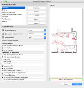
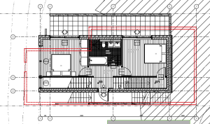
Use Renovation Filters to display your project to reflect different stages of renovation (such as “Demolition Plan” or “New Construction”), to control display properties based on the Renovation Status, e.g. to differentiate new from old Elements.
Archicad and Smart Template Template come with several predefined Renovation Filters, but you can change the options at Document > Renovation > Renovation Filter Options.
In any given Renovation Filter (such as New Construction), all elements of a particular Renovation Status (such as “New”) are displayed in the project in a particular way:
Show the elements with their default display, or
Hide the elements, or
Show the elements with an Override
As a result, as you switch Renovation Filters, elements are displayed differently, depending on their Renovation Status.
Renovation Filters use Graphic Override Rules to modify the display of elements, Rules regarding the Renovation stage are located at the top of the Graphic Override Rules dialog box.
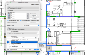
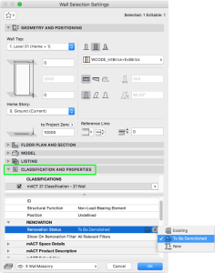
To assign a Renovation Status to an elements in your model use the Renovation Palette or Elements settings dialog box (under the Classification and Properties panel).
INFO > The Renovation Filter overrides Model View Options.
8. Floor Cut Plane Settings
3D construction elements on the Floor Plan (Walls, Curtain Walls, Columns, Beams and Roofs) are displayed as if they are cut horizontally along a theoretical plane; this is the Floor Plan Cut Plane.
Floor Plan Cut Plane is used for both Plan and 3D Document type drawings, such as Reflected Ceiling Plans and is usually a default setting unless you customise this for a particular reason in your project, e.g. when dealing with split level arrangements.
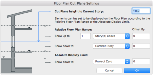
The default height of the Floor Cut Plane, is measured from the base of the current story, depends on local architectural conventions, but you can set any Floor Plan Cut Plane for the current window using the Floor Plan Cut Plane dialog box
To set the Cut Plane, go to Document > Floor Plan Cut Plane
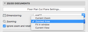
10. Zooming
The zoom level a specific view is saved with.
A view’s saved Zoom value includes the Pan and the Oriented View (rotation), if set.
Zooming Options are:
A. Current Zoom: The view will save the current zoom as part of its settings. Once a view is saved at “Current Zoom,” that setting is henceforth called Zoomed Area in this pop-up list.
B. Fit in Window: whenever you open this view, or whenever drawings from this view are updated or published, they will be displayed to include the project window’s entire content, subject to Layer status.
Any custom-named Zoom you have saved earlier (Current View by default).
C. Ignore zoom when opening this view: If this box is checked, then whenever you open this view, it will be displayed using the zoom value of the last opened Archicad window (not the saved zoom of this view). However, the saved zoom level of this view will still be applied when you place this view as a Drawing in the Layout Book, or publish it via Publisher.
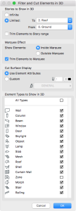
11. Filter and Cut Elements in 3D
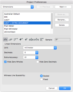
3D view filtering Criteria.
Criteria Options are:
Stories to Show in 3D: Define the range of stories of the project to be displayed in the 3D window.
Marquee Effect: If you have used the Marquee tool to create a selection area prior to generating the model, use these options to define which part of the project will be shown in the 3D window.
Cut Surface Display: Use these controls to define the surface and pens for the interior surfaces and edges of 3D Cutaways.
Element Types to Show in 3D checkboxes allow you to turn the 3D Window display of construction elements on and off. With Doors and Windows switched off, openings are interpreted as empty holes. Checking the All Types box selects all element types.
12. Generate In
Defines what Render Engine the 3d view will be generated in.
Options are:
• 3D Window
• PhotoRendering Window
12. 3D Style
A 3D Style is a collection of 3D settings (3D Engine, shading, background, etc.) that determines model display in the 3D Window.
Affects the view only if you select 3D Window in Generate In: filter.
14. Rendering Scene
A Rendering Scene is a set of predefined Rendering Settings that can be stored and re-applied using the Select and Manage Scenes dialog box.
Affects the view only if you select PhotoRendering Window in Generate In: filter.
To setup PhotoRendering window for a View in combination with Publisher can be particularly convenient for Batch Rendering.
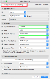
Get Current Window’s Settings
If you click this button, the settings in the View Settings dialog box will be overridden to correspond to the currently active View Settings in the active window and its active filters.
This can be tricky because if your View doesn’t use predefined filters (Layer Combinations, Pen Sets, Model View Options, Graphic Override,…), the filter in View Settings will be recorded as Custom. We strongly discourage using Custom filters as at the end of the day you will not remember what a Custom filter for particular View includes, not mentioning your Teamwork members.
Best practice is to always create and name or update relevant filter combinations, so everyone in your office / team can understand or re-apply new/updated filter combinations to other Views.
INFO > Access Project Preferences>Legacy…. to control the overhead and hidden structure line types on global level.
macinteract Pty. Ltd. | ABN 44 155 154 653 | terms and legal. | © 2025
