macinteract Pty. Ltd. | ABN 44 155 154 653 | terms and legal. | © 2026
SketchUp provides a number of drawing aids to help you draw accurately and relate to where in the three dimensional workspace your cursor is located.
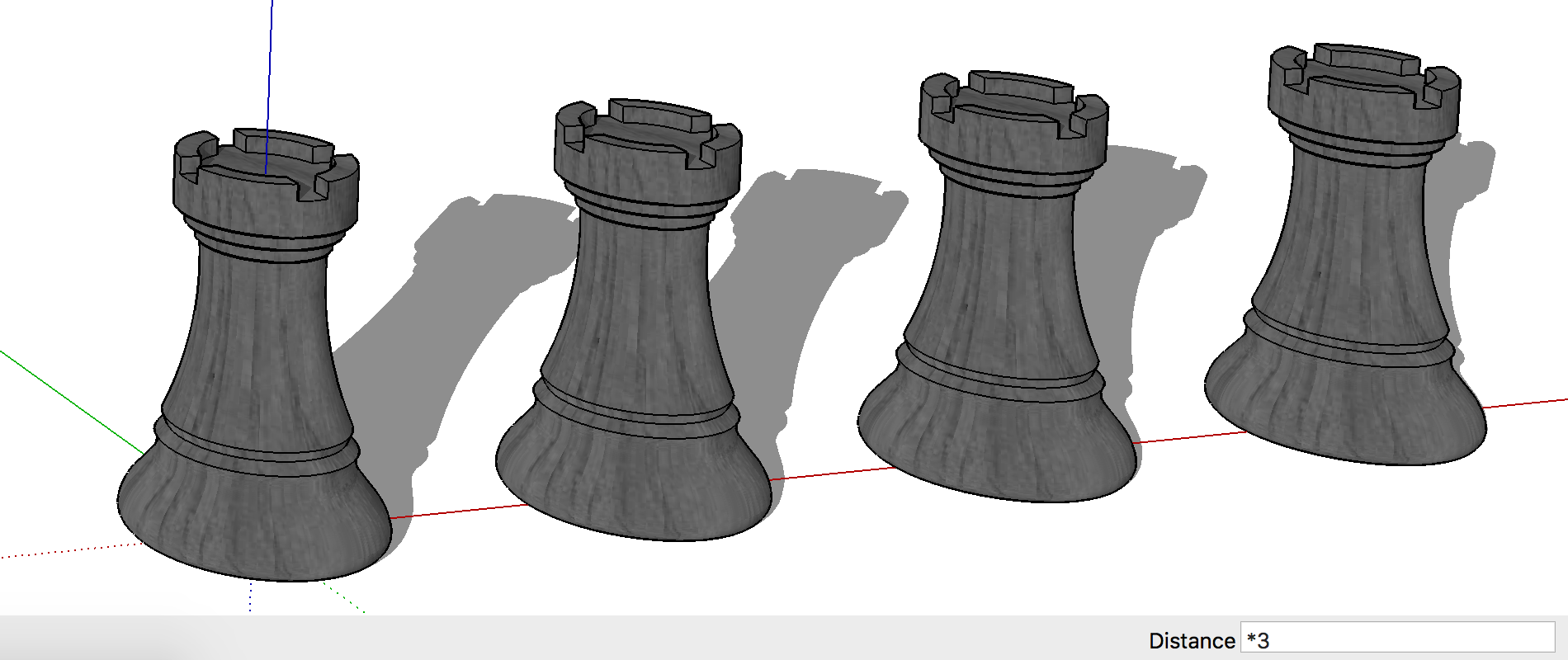
The Measurement Box at the bottom right of your screen is a fundamental tool for creating accurate models. It is an input field for dimensions. You can enter precise values into the Measurements Box once you select a tool. Note the values you can enter depend on the active tool, it allows input of numerical dimensions (rectangle dimensions, distance, radius, angle, scale, sides for polygons,etc). It can also be used to create evenly spaced copies of entities, e.g. to create 3 copies, start by moving a copy the desired distance, followed by *3.
INFO > Input is relative to the starting point, i.e. the first click and not the origin!
Until you start a new procedure or activate another tool you can correct your numerical input as many times as you like.
Guides or guide lines are temporary dashed lines to guide you to model accurately.
Use this for:
Creating guidelines that are either parallel, perpendicular or an extension of an existing element.
Where to find:
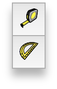
1.1 To create linear guidelines activate the Tape Measure tool : Tools > Tape Measure. Press the Option-key to activate guide mode (indicated as – + symbol next to tool icon), click and drag from an edge or point. Use numerical input for exact dimensions.
1.2 To create guidelines that are angled to an edge activate the Protractor : Tools > Protractor. Click and drag on a point to set the axis. Click the second reference point to define the line to angle from. Enter a numerical dimension or snap to a point.
TIP > To delete all guides from your model go: Edit > Delete Guides.
Every SketchUp template contains a set of predefined settings for scene and units of measurement.
By default, the ‘Welcome to SketchUp’ dialog box will pop up when you open SketchUp, where you can select the right template for your design.
We recommend to start with the Architectural Design – Millimeters Template if you intend to use SketchUp for architectural projects.Inferencing is the most powerful drawing aid in SketchUp. It helps you navigate through the 3D space and draw elements related to the drawing axis or related to each other. It locks the cursor in relation to any element in your SketchUp model.
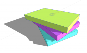
There are 3 inference types: Point, Line and Shape.
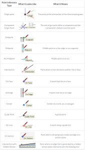
Point Inference:
Point references are based on the location of your cursor. SketchUp will automatically snap to surfaces, edges, endpoints, midpoints, faces and intersections. To indicate the snapping mode the cursor will turn diamond, square, round or round with a dot at the centre respectively .
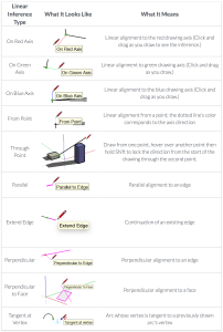
Linear Inference:
SketchUp will constrain to the three axis when drawing parallel to them as well as to the extensions of lines. You will see this happen when the line that you draw will change colour corresponding to either one of the axis colours or pink in case you are extending a line.
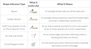
Shape Inference:
Use this inference when you are creating a shape and looking for specific proportions. For example SketchUp will indicate a Square or Golden Section proportion inference when drawing a rectangle.
Note where you exactly draw in space is dependent on the view that is displayed in the 3D window. Try drawing the first point of a rectangle. Now notice the automatic constraints change when you change your view (Orbit tool, MIDDLE mouse button) from looking down on the ground to looking more perpendicular to green axis to more perpendicular to the red axis.
The rotate tool cursor will turn red, green or blue before you click the first point to tell you when you’re drawing perpendicular to the respective axis.
TIP > To help rotate elements perpendicular to the respective axis, draw a temporary rectangle next to your model and use its respective surfaces while holding the Shift-key to lock red, green or blue direction of rotation.
Besides these automatic constraints you can force (lock) constraints.
For example, when you want the second point of a line to be on a line you have drawn before, hover the cursor above the line that you want to constraint to and hold down the Shift-key. You will notice that the line you are drawing will be displayed fatter. While holding the Shift-key move the cursor around. Notice how the second point of your line you are drawing is constrained to the existing line and its extension. SketchUp will also still snap to other points.
You can also force constraints to any of the axis by pressing the arrow keys on your keyboard; UP for the blue axis, RIGHT for red and LEFT for green.
INFO > Locked axis (x,y,z) constraints are the most reliable as you won’t be snapping to an element that might not have been drawn correctly in the first place!
TIP > The Axis tool allows you to re-orient the default red, green and blue axis. This is helpful when you want to draw elements in different orientations, for example part of your model is rotated by a certain angle versus the rest of the model. Note that the Axis orientation within groups or components can be different to the axis orientation outside of groups or components.
3 minutes 11 seconds
video by @SketchUp
macinteract Pty. Ltd. | ABN 44 155 154 653 | terms and legal. | © 2026
We use cookies to keep things running smoothly and help us improve—no secrets here!
Please select which cookies we can use. You can change your mind whenever you like!
Websites store cookies to enhance functionality and personalise your experience. You can manage your preferences, but blocking some cookies may impact site performance and services.
Essential cookies enable basic functions and are necessary for the proper function of the website.
These cookies are used for managing login functionality on this website.
Statistics cookies collect information anonymously. This information helps us understand how visitors use our website.
Google Analytics is a powerful tool that tracks and analyzes website traffic for informed marketing decisions.
Service URL: policies.google.com (opens in a new window)