macinteract Pty. Ltd. | ABN 44 155 154 653 | terms and legal. | © 2026
Standard Archicad comes with a library containing more objects than you will need for a project.
Using objects has many benefits such as standardisation, reducing file size and the ability to schedule them.
Most objects however have more settings than you will ever want to worry about.
TIP > Set up objects with settings as needed as part of office standards / template and save them as Favourites. This will save all team members a lot of time and overall reduce the margin for error. See the chapter on Office Standards for more details on Favourites.
Type 1 : Embedded Libraries.
Objects in this library will only exist in one Archicad file; if your project consists of multiple linked files, having parts in this library should be avoided.
New objects when created from the plan view will automatically be added to the embedded library. Save these to a designated linked office or project library on the server before deleting them from the embedded library.
Type 2 : Linked Libraries.
Linked libraries are located either on your computer or on your server when you have an office or project library set up.
These libraries can be loaded into any Archicad file and are not restricted to a single file, user or project. Typically they are contained in a lcf-file, which stands for Library Container File. However you can also load regular folders. The lcf (as it can be compressed) will usually be quicker to load.
Type 3 : BIM Server Libraries.
Available when you have a BIM server setup and you are using Teamwork. BIM server libraries will still be linked to a location on your server or computer, depending where it was uploaded from, to the BIM server.
That means when new parts are added to the server then your BIM server library will need to be updated before they can be used through the latter.
Check, add (upload), relink, remove and refresh libraries through the Library Manager: File>Libraries and Objects> Library Manager.

INFO > It is possible access for this function to be restricted depending on user roles.
Where to find:
COMMAND + T with an object selected or the tool activated.
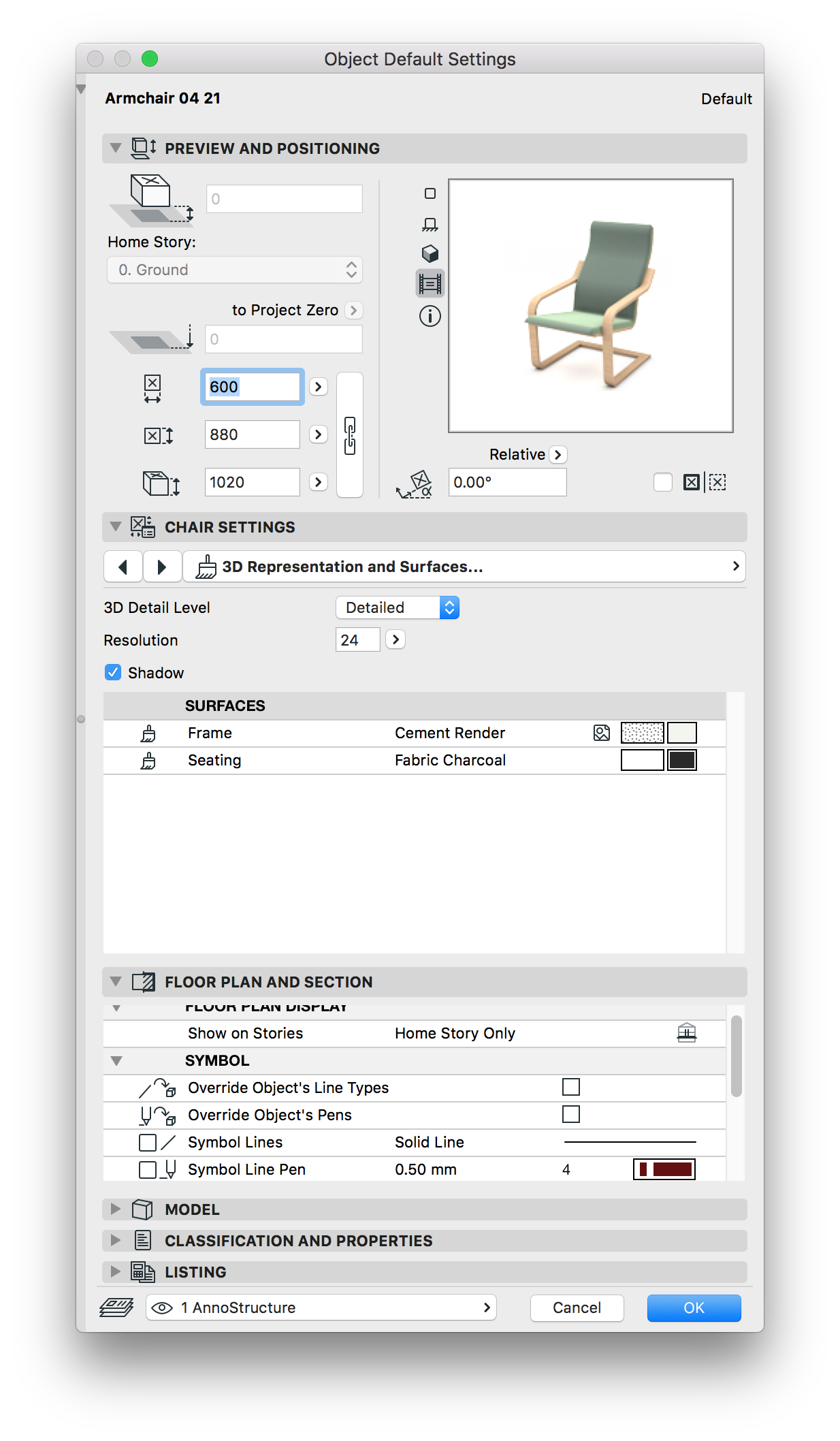
Most objects are parametric, meaning that through the settings window you can, for example, control their size and how they display.
Make yourself familiar with the settings window. Its available content will depend on the selected library part.
INFO > Parts of the various submenus can overlap in their settings.
On the left side of the settings window you will find navigation and a general / static object preview, on the right side settings for the selected object:
TIP > It is possible to inject current parameters into a different object.
1. Pick up parameters from an object (OPTION + click)
2. Open the object settings window
3. Select a different object by injecting parameters: COMMAND + OPTION + click its icon in the settings window.
Objects can be scale sensitive, changing their representational level of detail depending on the scale of your drawing.
When using objects think about how much detail you need to show for a schematic representation of reality.
It is very easy to overdo it!
Where to find: Document>Set Model View> Model View Options
Through the model view options linked to your saved view it is possible to globally override some display options of objects.
For example you can hide doors and windows and only show their opening for Reflected Ceiling Plans or override cut fills to show as solid to use in sketch or design phase where you don’t want to show the full detail of the cut fill.
Typically you would have a Model View Option set up per drawing type in your set.
Objects can be scale sensitive, changing their representational level of detail depending on the scale of your drawing. When using objects think about how much detail you need to show for a schematic representation of reality. It is very easy to overdo it! For many Library Parts having a three dimensional representation is a benefit, but not a necessity.
To reduce file size and speed up your computer have the object display as 2D only.
INFO > You can use the model view settings to hide knobs, taps and handles.
macinteract Pty. Ltd. | ABN 44 155 154 653 | terms and legal. | © 2026
We use cookies to keep things running smoothly and help us improve—no secrets here!
Please select which cookies we can use. You can change your mind whenever you like!
Websites store cookies to enhance functionality and personalise your experience. You can manage your preferences, but blocking some cookies may impact site performance and services.
Essential cookies enable basic functions and are necessary for the proper function of the website.
These cookies are used for managing login functionality on this website.
Statistics cookies collect information anonymously. This information helps us understand how visitors use our website.
Google Analytics is a powerful tool that tracks and analyzes website traffic for informed marketing decisions.
Service URL: policies.google.com (opens in a new window)