B1-5
Layout Book Setup
Introduction
Depending on the size of your project, the layout book might be located in a separate file.
In this case a Publisher Set should have been set up in your Main File to save out PMK’s to a folder specified by you on your project server. Consequently instead of using an internal view to be placed on a layout, you will have to place an external drawing and point it to the relevant the pmk- file.
Layout Book
The Layout Book is a tree view of all the Layouts defined for the entire project, plus all Drawings placed on each Layouts. The Layouts are like virtual sheets of paper where Views from the View Map (drawings, 3D perspectives, lists, schedules, etc.) are placed on.
In the Layout Book, you can organise Layouts into subsets (represented by folders).
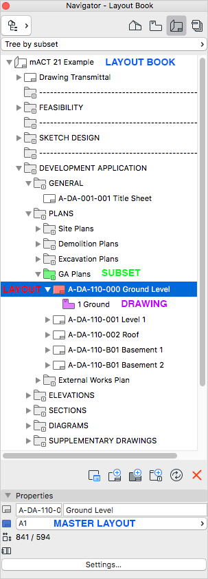
TIP > Organise the layout book into sets and subsets relating to design stages and drawing set type. As example a DA Drawings set, contains subsets of Diagrams, Floor Plans, Elevation, etc.
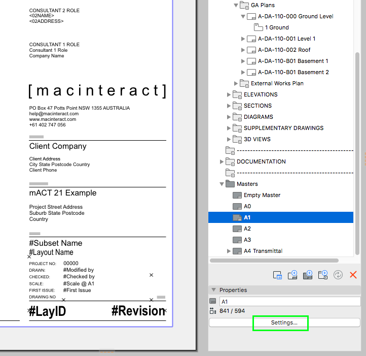
Master Layout
Where to find: Navigator > Layout Book tab > at the bottom of the tree.
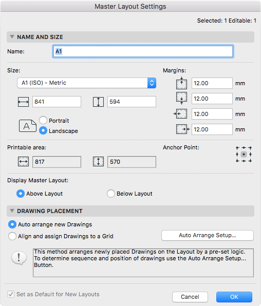
Master Layout Workflow
Right Click on any Master Layout > New Master Layout
Select the Master Layout and click Settings…
Define as required.
Draw 2D info directly on the Master Layout. Ensure everything is on the (always on) ARCHICAD Layer.
A Master Layout needs to be assigned to every regular Layout and contains information that is used on many regular layouts. This information is typically your Title Block.
The Master Layout also defines the paper size of your regular Layout sheet. This means that you have to set up several Master Layouts based on required paper sizes.
To summarise, these are the conditions that define which Master Layouts you need to set up:
Title Block.
Only if different Title Blocks are used for the various design stages of a project.
Paper Size.
North Point.
In case you choose to include the North Point on the Master instead of on relevant Layouts you will need to also set up Master Layouts without a North Point, as drawings such as Sections and Elevations don’t require a North Point.
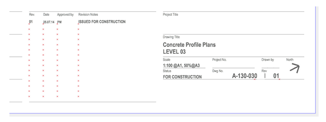
Title Block
The most common approach to add a title block is to draw it on a Master Layout. For good or bad, this is easy for anyone to modify.
The title block placed on the layout can be an object that is automated to allow for usage of details entered into project info, scale display and display of revision number or simply 2D info on a Master Layout.
The title block can also be a custom made object , which is subsequently placed on relevant layouts directly. This requires some advanced scripting knowledge to code however. The advantage is that easy editing isn’t possible, however in most cases the straightforward 2D drawn title block on a master layout should be a great solution.
The title block can be set up to include, for example:
Autotext blocks to allow for usage of details entered into project info,
Autotext blocks to show scale of drawings on layout.
North Point
Disclaimer
Logos
Hotspots to facilitate placement and sizing of drawings, text, North Point, Revision Info, etc. on Layouts.
North Points that read the orientation from the Project Preferences can be placed on a Master Layout, however note that drawings like Sections and Elevation do not require one.
TIP > Images, such as logos, should be converted to Fills, Lines, Text when possible. This has a few advantages:
reduces the size of your published files,
exported DWG’s will contain the actual vector based graphic instead of linking to an image that might or might not be included,
will be readable even if scaled (enlarged images can get fuzzy).
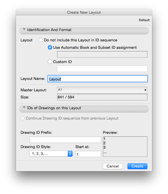
Create a Layout Workflow:
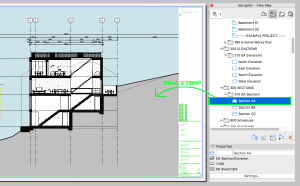
Create a New Layout by right-clicking on the appropriate subset and choosing New Layout, or by selecting the New Layout tab (2nd from left) at the bottom of the Navigator panel: (Image 1)
This will open up a new window in which you:
name the layout according to your project naming conventions
select the Master Layout as required (this contains your titleblock)
Select the ID numbering style for drawings which will be placed on the layout.This will be automatically linked to the drawing title of your placed PMK(s) should you choose to display it.
click Create.
(Image 2)

Placing Elements onto a Layout
Drawings are Archicad views (from the View Map) or external files that have been placed directly onto a Layout. Drawings can be created from views from the current project file, or imported from external Archicad project files
External drawing and picture files as well as PDF files can also be placed directly on a layout. All these placed items are collectively called Drawings.
2D Elements:
You can use a limited amount of elements from the Archicad Toolbox (limited to 2d Tools and the Object Tool). Best practice is to keep additional elements placed directly on a Layout on the Archicad Layer (which is a special Layer that is always visible in any Layer Combination).
Placing Drawings:
Drawings can be placed on layouts separately or collectively in the following ways:
Drag and Drop View from the View Map in Organiser or Navigator Palette
With the Layout window active, go to the Navigator Palette or Organiser, and drag and drop one or several items directly onto the layout
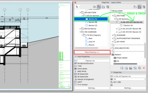
In the Organiser’s Layout Editor, drag and drop items from the View Map into the Layout Book on the right side. (Or use the Place Drawing command on the left side of the Organiser.)
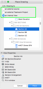
With a Layout window active, activate the Drawing tool from the Toolbox, then click on the Layout. From the appearing Place Drawing dialog box, choose one of the following options as the Drawing source:
an internal view: The current project’s View Map is shown in the dialog box. Select a view, then click Place. (The filters = properties of any selected view are displayed in the View Properties panel below.)
an external source: Click Browse to locate the Drawing file using a directory dialog box.If you choose an Archicad project file, the Place Drawing dialog box appears again, listing the View Map of the chosen project. Select a view, then click Place to place it on the active Layout window.
an external Teamwork Project: Click Browse. In the appearing Select Teamwork Project dialog box, choose the server and the project you need. The Place Drawing dialog box appears again, listing the View Map of the chosen project. Select a view, then click Place to place it on the active Layout window.
Place Drawing from an External Application:
Use the File > External Content > Place External Drawing command
From the appearing Place Drawing dialog box, select a drawing file from the file system. (The PDF format, many image formats, DXF and DWG are among the available formats.) Click Open. If you want to import drawing from a solo Archicad project select an Archicad file type (PLA, PLN, BPN). The Import views from Archicad Project dialog box appears. Choose the view(s) to import and a method for adding them to the Layout Book.
Use the File > External Content > Place External Drawing from Teamwork Project to import Drawing from a Teamwork project

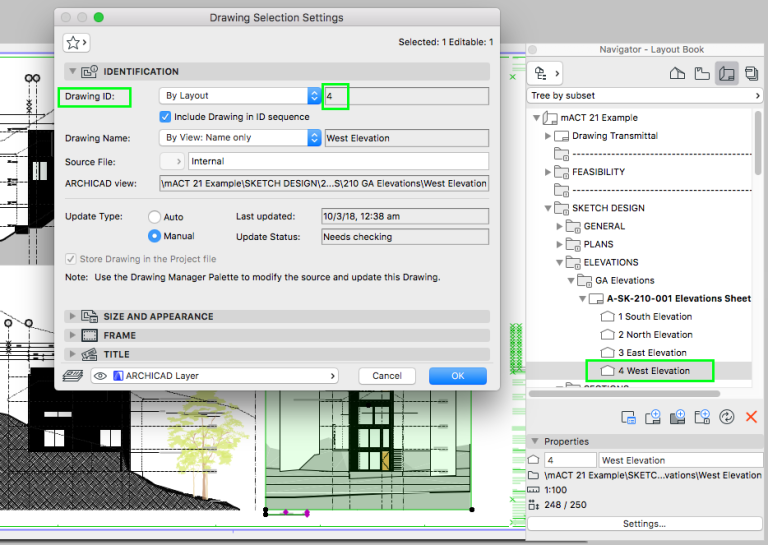
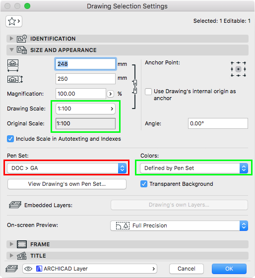
Drawing Settings
In this paragraph we will highlight only few items out of many from the Drawing Settings dialog. You can add as many drawings and 2D elements onto a Layout as required
Drawing boundaries can be cropped as required.
Both Layouts and Drawings have IDs assigned to them, as an aid in organising, navigating and outputting your project. The primary use of assigning Layout IDs is to achieve automatic numbering of the Layout Book. While an automatic logic can be applied to the whole Layout Book, Archicad provides maximum flexibility in customising the assignment of IDs to meet your preferences.
You can overlay multiple Drawings on the Layout and combine more Views to achieve desired look, to be able to see through layers of Drawings keep the Transparent Background Option ticked on.
Drawing Scale: By default, this field indicates the scale of the drawing as defined in its Archicad source view. Customising the Drawing scale has no effect on the scale of objects within the drawing; it is equivalent to a graphical resizing of the Drawing, like the effect of magnifying a document with a copy machine.
Original Scale: This field provides feedback on the scale of the drawing’s source view
Pen Set: In Drawing Settings, you can re-define the assignment of pen sets to placed Drawings (differing from View Map)
Colors: By default, a Drawing will display the colours as defined in the pen set from View Map settings. However, a further override options are available: Grayscale or Black & White as a uniform colour setting, for this drawing only
TIP > You can duplicate an entire folder of drawing layouts. For example, if you already have a folder containing your general arrangement drawings in the layout book, you could clone the folder numerous times to make sets for your concrete profiles, RCP’s etc. Also, should you want a set of GA’s at another scale, clone the folder instead of setting every drawing up individually. Remember to relink the PMK’s to the settings saved for these drawings in the View Set, and change the drawing number!
To set up multiple drawings, set up the first then duplicate that as many times as required. Relink the drawings on the sheet to the correct views.
Organise the layout book into sets and subsets relating to design stages and drawing set type. As example a DA Drawings set, contains subsets of Diagrams, Floor Plans, Elevation, etc.
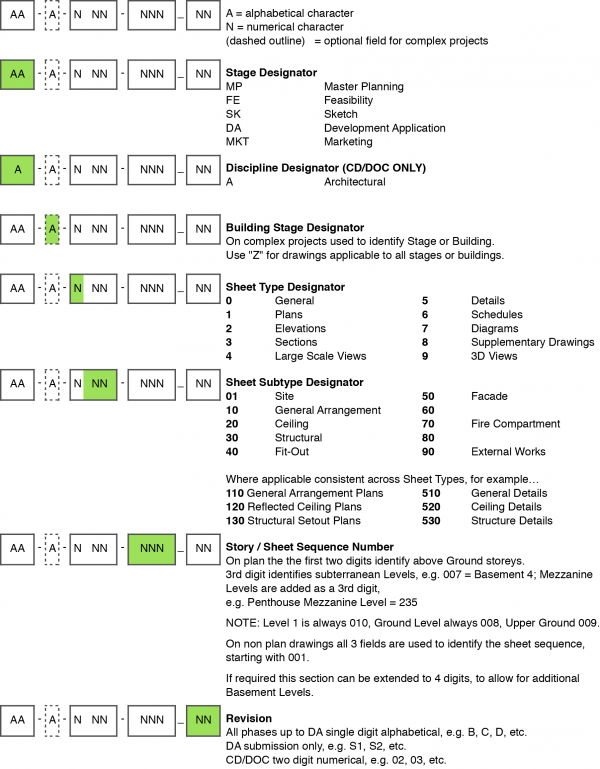
Drawing Numbering System
We recommend using a drawing numbering system which is based on the United States National CAD Standard as it provides a logical system which is scaleable to any project size.
TIP > Should your Layout Book be located in a separate file due to the size of your project, ensure that a Publisher Set is set up, from which you will save out PMK’s from the main file to a specified folder on your project server. As a result, instead of placing an internal view on your layouts, you place a PMK from this folder on the relevant layout as an External Drawing.
Drawing Manager
Where to find: File > External Content > Drawing Manager
Use this to: Update drawings, both internal and external.
TIP > Keep drawings as manual rather than automatic update where possible, especially with external drawings in Autocad (DWG, DXF) format. This will speed up start up, shut down & saving time and general interface with Archicad.
Also, very importantly, it gives you control over when to update your drawings.
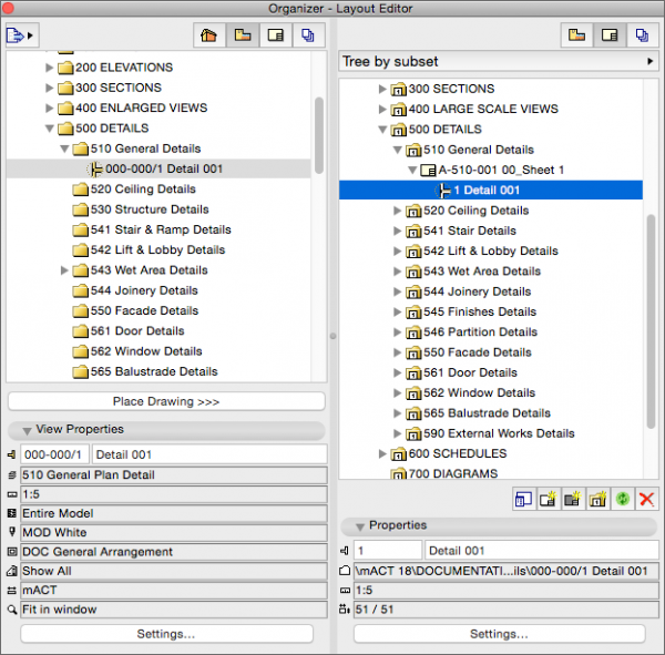
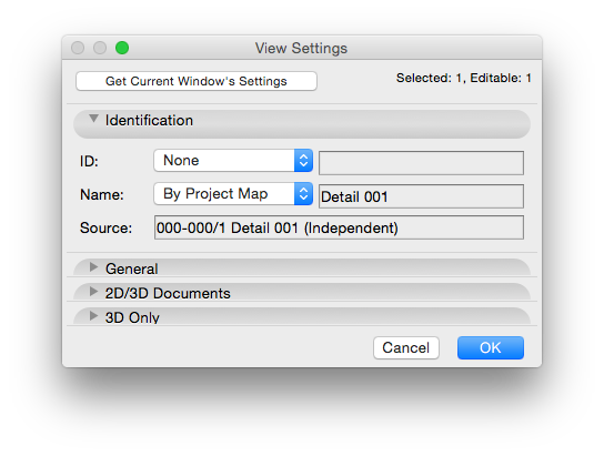
TIP > In View Map, select the relevant Details and go Settings. Set ID as “None” in the View Settings Palette. This will list all your placed details by Name only and omit the automated ID.
CAUTION > Do not move detail drawings to a different drawing sheet after they have been placed, as this will cause inconsistencies in your documentation. This is especially important once drawings have already been issued to consultants and/or subcontractors.
Revisions
Archicad 18 Introduced a new way to manage revisions which is integrated into your modelling and layout-ing workflow. It will, however, not append the revision number to your file name and can be more work than necessary.
Since Archicad 19 Layouts can have user defined autotext fields. If you want to keep your revision setup as straightforward as possible you can define a new autotext field in Book Settings (Navigator > Layout Book > Right click top item > Book Settings), which will then be available for all Layouts. If you set up an Index Schedule that lists all Layouts (ideally per set), you can include this newly created revision field and update it via the index rather than going through every individual layout.
Archicad 18 Introduced a new way to manage revisions which is integrated in your modelling and layouting workflow. It will, however, not append the revision number to your file name and is less straightforward, but also more powerful, than the Smart Templateify object described at the end of this chapter.
Depending on local requirements various approaches to adding Revisions may be used, e.g. in Australia typically, the following is sufficient:
– Layout sheets typically show the revision number in their respective Titleblocks, usually next to the Drawing Number / Layout ID.
– A short description of the individual Revisions is added to a Revision history in the Titleblock area.
In our experience appending the Layout ID with the Revision identifier directly in the Layout Book, allows for simplified tracking of Revisions directly inside Archicad and for any published files. Please note however that this may require a custom GDL object to separate the Drawing Number / Layout ID, e.g. if you wish to graphically separate them in your Titleblock.
Revision notes will need to be entered and updated manually directly on the sheet itself. Ensure your title block has hotspots placed to help you position your notes consistently on the sheets.
INFO > The following only works with the Smart Templateify Layout Name & Revision object.
Revisions are appended to the Drawing ID in the Navigator, they need to be separated from the Drawing ID by an underscore, and then get displayed automatically in the titleblock object.
macinteract Pty. Ltd. | ABN 44 155 154 653 | terms and legal. | © 2026