macinteract Pty. Ltd. | ABN 44 155 154 653 | terms and legal. | © 2026
During the early stages of a project, typically during Feasibility or Design Development, the relevant site restrictions are set in place for your project. These restrictions vary according to the local government or council requirements, and can include:
1. Site Boundaries
2. Setbacks & Easements.
3. Height Plane.
Without resorting to custom made objects, there are two methods of drawing the Site Boundary in your file. In Plan, the workflow is essentially the same for both methods. The main difference lies in how this is drawn in the Elevation & Section windows.
1. Using Lines or Polylines.
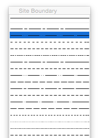
In your plan view, Trace & Reference the survey worksheet and trace the boundary using either Lines or a Polyline. Use the tracker for input. Assign a suitable line type with a sufficient pen weight for maximum clarity in your drawings.
Similarly, use Trace & Reference on sections and elevations to draw site boundaries in the correct location. To find the correct location ensure that the relevant section or elevation marker is showing in the Trace & Reference. It should be located running through the origin (indicated by the “x” in your 2D view). The cursor should snap to the intersection between the section / elevation line and the site restriction lines as drawn on plan and seen in the Trace & Reference.
2. Using Grid Elements.
In your plan view, trace the boundary as with Lines / Polylines, but instead using Grid Elements.
The advantage in using the Grid Element Tool is that in your Elevation and Section windows the Site Boundary will display automatically without you having to trace their location in each window. Note that in your section or elevation settings you do need to tick Display Non-Perpendicular Grid Elements in the Grid Tool tab!
AC-B33
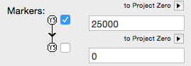
Ensure you assign an appropriate height in the Section/Elevation panel, and deselect displayed Markers. Remember to lock the elements as well as their layer to avoid accidental editing once you are done drawing them.
TIP > Draw the Site Boundary in a separate file and hotlink this into your main file.
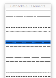
As with the Site Boundary, in your plan view Trace & Reference the worksheet containing the Survey, and trace any setback lines, easements etc. Ensure a suitable line type is used to easily distinguish these from the site boundary. Annotate accordingly. Once again follow the same workflow as with Site Boundary in any relevant elevation and section windows.
TIP > For setbacks which are parallel to the site boundary, trace the boundary with a polyline (“P”) in offset mode (“U”). Use the tracker for numerical input.
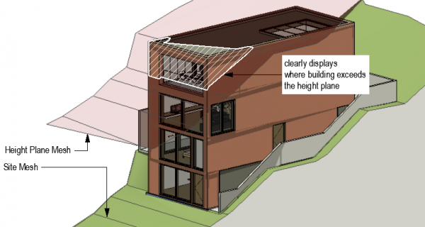
In most urban areas there is a height restriction in place which restricts the maximum vertical height of a building or development, which must be strictly adhered to. This can be for many reasons, including impact on views, overshadowing of adjacent properties etc. Typically, since most sites are not flat, a simple horizontal plane reflecting this limit is not an option, and this height plane therefore needs to follow the contours of the site. This is a very easy process to set up.
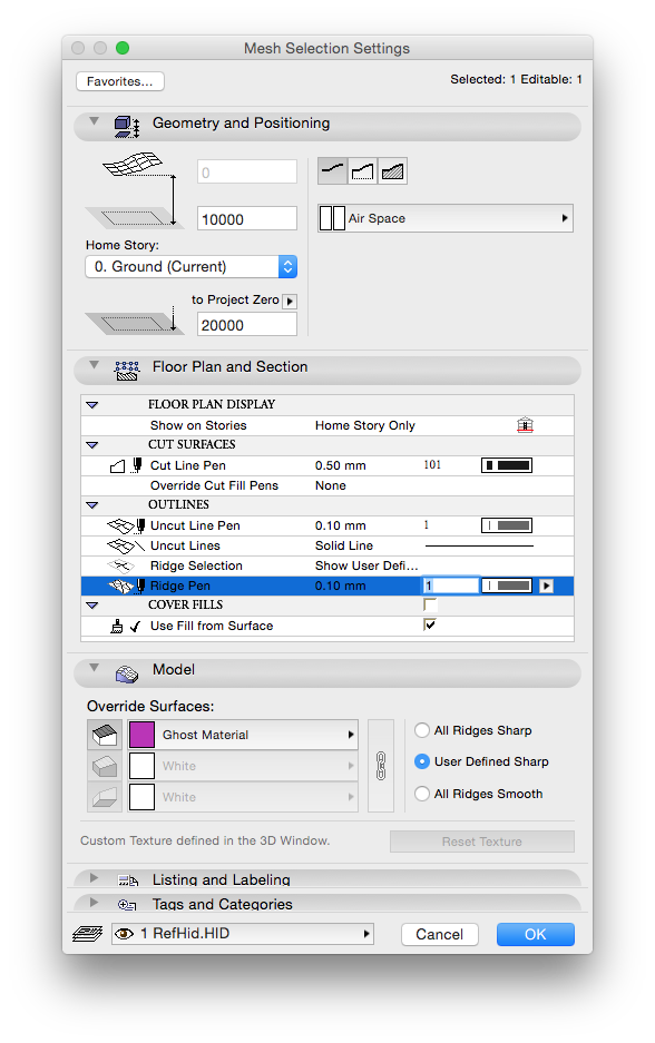
With the site modelled in 3D (as described in the previous chapter) you can make a copy of the mesh and simply elevate it to reflect height restrictions. Place this mesh on a suitable layer, e.g.. RefHid (that is typically turned off) and apply the following settings for clarity:
1. Allocate a translucent material with an easily identifiable colour, e.g. translucent red. This gives clear indication in 3D where you are exceeding the height restriction.
2. In the Geometry and Positioning tab, change the Mesh to display Top Surface only by clicking the left most of the three icons.
3. Change the Cut Line Pen to enable you to easily identify it in your view.
4. In your sections and elevations, trace the mesh as required using a polyline.
TIP > If you render the elevation with the Height Plane Mesh having a solid fill (instead of just a plane). You can select the 2D Fill it generates (Instead of the lines) and copy it. Re-render the view with the Height control mesh layer hidden, and then paste in place the 2D Fill. You can now apply appropriate parameters of lineweight, linetype, layer, etc. to quickly generate a height control line in your elevation. This can be faster and more accurate than tracing with a polyline.
macinteract Pty. Ltd. | ABN 44 155 154 653 | terms and legal. | © 2026
We use cookies to keep things running smoothly and help us improve—no secrets here!
Please select which cookies we can use. You can change your mind whenever you like!
Websites store cookies to enhance functionality and personalise your experience. You can manage your preferences, but blocking some cookies may impact site performance and services.
Essential cookies enable basic functions and are necessary for the proper function of the website.
These cookies are used for managing login functionality on this website.
Statistics cookies collect information anonymously. This information helps us understand how visitors use our website.
Google Analytics is a powerful tool that tracks and analyzes website traffic for informed marketing decisions.
Service URL: policies.google.com (opens in a new window)