B2-4
Grid Setup
Grid Tool
Where to find: Toolbox > Grid Element Tool
Design > Grid System
Use this to: Grid lines are an integral part to any drawing, whether used for setting out your building at a preliminary stage, or as a means of setting out your building during construction. It is essential that grids are placed accurately as early on in your project as possible.
A good, safe method to consider using, is to set up a Set Out Grid system for a project at say, Design Development stage in a Set-out file and Hotlink it in to your Main file as a single story Module. This will prevent accidental editing or deletion. Place it on a dedicated Master Layer, which can be turned off for Design Development documentation printing. This grid can be edited later as required at construction docs stage, and the layer combination simply changed to display it on your drawings.
INFO > Although grid lines can be set to display on multiple stories, their associated dimensions can not. Place your Module on every relevant story and then lock it. Ensure the height required for display of the grid lines in section and elevation is set in the Elements File as it can not be edited from the main file. Go: Grid Element Settings > Section / Elevation > Set top and bottom values relative to Project Zero: Typically you would only display the top Marker bubble.
There are several criteria that need to be considered when setting out your Grid:
1. Set-out point
In most cases your grid system will be set out orthogonally, in other words at 0 and 90 degrees, and incrementally. When setting out your grid, establish a suitable set-out point from which to start. This can be either from or relevant to, say, a site boundary or from a known, fixed point. Should you choose the latter, ensure that this point will not move in the future, for example, a point identified in the site survey such as the peg at the intersection of two site boundaries.
As a good rule of thumb, set out your drawing so that one of the site boundaries is either horizontal or vertical (if possible), and use this boundary as a starting point from which to set out your grid. Allow for some tolerance. If close to the boundary, start the first grid at an offset of 50 or 100mm from the boundary to allow for tolerance. Thereafter build the grid at either repeating, regular increments or alternatively at known distances based on your column or structural wall set-out.
2. Grid tool vs Grid lines
Grid lines can be drawn using several tools. The line or polyline and text tool is always an option, but remember that should you choose one of these, your grid lines will have to be drawn again in every section, elevation and plan view by means of either copy / paste or by using trace & reference to locate them accurately. There is a good change of inconsistencies in this basic 2D method.
A better as well as obvious choice is to use Archicad’s inbuilt Grid Lines tool. The advantages are that every placed grid line is able to display on multiple stories, on all elevations and sections, as well as (should you so desire), the 3D window.
Discussed below is also the Grid System tool. However, as it is known to ‘break’ once individual lines are edited in the model, using the Grid Lines tool is preferred.
Section & Elevation
As mentioned previously, Grid lines drawn in plan can be set to display in the section and elevation window. This will ensure accuracy and negate the need to draw them again in each view. In the Section/Elevation tab, set the line type, pen colour and height of the marker in relation to project zero.
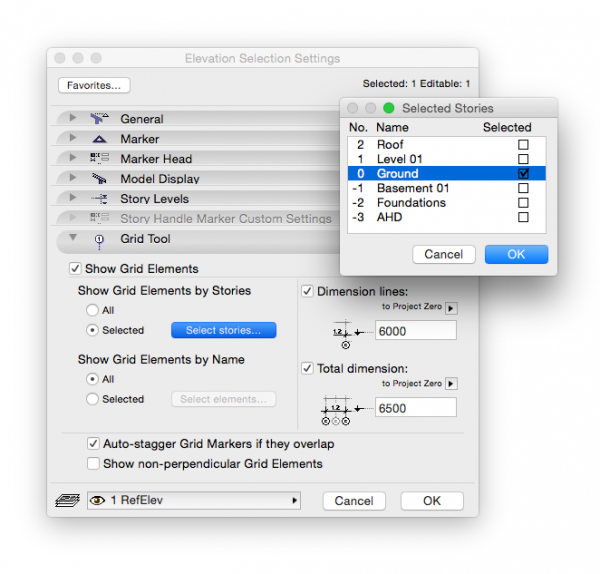
TIP > When using a grid in hotlinked MOD method, ensure that you set the display of Grid Lines in your Elevation and Section Settings to one selected story only to prevent multiple overlapping / offset instances of the grid lines. Note that this needs to be set per section and elevation! Select and Right Click the relevant section(s) or elevation(s) in the Navigator’s Project Map > Settings and go to the Grid Tool tab.
3. Grids in the 3D window
Showing grid lines in 3D can be useful at consultant coordination meetings, where displaying grid lines helps locate complex parts of the model and facilitates communication regarding detail resolution and clash detection. Note that accurate drafting should still only be done in 2D.
Should you choose to display your grid lines in your 3D window, the method is as follows:
In the 3D View tab, tick Display in 3D view.
Tick Show as line.
Select a surface to represent the colour of your text in the marker bubble.
4. Grid Line Placement
Ideally, establish your grid line system as early in your project as possible. Always use the correct layer from the start, and remember that it is possible (and recommended), to use different grid systems depending on the project stage and drawing type. In the Smart Template template, there are numerous grid layers, namely:
Grid Clg – used for ceiling tile grids (typically in the construction documentation stage).
GridFac – used for setting out complex facade systems (also typically in the construction documentation stage)
TIP > The ceiling and facade grid systems are typically secondary grids, and do not replace your construction grid. These should each be assigned a different and clearly identifiable numbering system to enable them to be displayed alongside the construction grid. (e.g. CA/CB, C1/C2 etc. for ceiling grids, and FA/FB, F1/F2 for facade grids).
GridSetout – used for setting out primary elements of construction in your project, and can be placed early on in your project as described above.
GridStr – this is your structural grid and is what you dimension your building to in order to set it out on site. This grid is critical and once established, should not be edited under any circumstances, especially once drawings have been issued to consultants!
Changing this grid after a certain point can have severe implications in terms of accuracy and setting out on site, as well as coordination between the various consultants should someone forget to update the new grid locations. For this reason we highly recommend keeping your grid system in a separate file and hotlinking it into your main file, to prevent accidental editing or deletion. Typically this grid will be the one established in consultation with your Structural Engineer.
TIP > Keep a placement locator (A Hotspot for example) in said hotlink, for a quick visual check that the Grid is still placed in the right location.
Place Hotspots at all grid intersections, enabling accuracy when dimensioning back to a grid line during the CD phase of the project
5. Grid lines can follow two main methods:
regular grid system, whereby a fixed offset distance is set in both directions. This is often the most suitable method during the Design Development stage, where the precise locations of structural elements such as columns is not yet known. For example, use a grid system of 5,000mm in both directions, and set your building out from there. This grid system can also be temporary and not displayed in drawings during the early stages of a project. Once CD stage begins and structure is determined, this grid system can be replaced by a structural grid.
A grid system based on structure. This should ideally be set out from the lowest story in your building, for example the centreline of the general column grid on the basement carpark. Do not be tempted to change this grid system from one story to another, regardless if the structure changes from one story to the next! Structure (concrete) gets dimensioned in the concrete profile drawings, and provided you dimension accurately, the offset to the grid lines from the centreline of columns does not matter. It is for this reason that we recommend that the grid system is drawn once, displayed on all stories and hotlinked in from an external file and locked.
Grid Systems Tool
Where to find: Design > Grid System Settings
Use this to: Archicad has an inbuilt Grid System tool in which all the aforementioned information can be entered, and will then place your grid system automatically into your project.
In addition, this tool also allows you to automatically place structure into your model (typically beams and columns) at the time of setting out the grid, as well as dimensioning it, and all with only a few clicks of your mouse. However, it can be buggy when single grid elements are edited individually instead of through the grid system tool! For that reason, drawing the grid with single grid lines is the preferred option.
To place a Grid System, proceed as follows:
1. Activate the Grid System by going Design > Grid System Settings.
2. Select your Grid Geometry, i.e. whether you wish to use an orthogonal or a curved Grid System.
Should you require a radial Grid, ensure that you set the radius (which is measured from the origin of the circle or curve, to the farthest radial grid line.
3. In the General Settings tab of the properties panel, set all the properties for the following:
grid lines
columns
beams
dimension style (individual and overall)
By selecting any or all of these, the relevant Settings tabs will become available which will open up the properties panel for each individual element. Set these in accordance with your office template and whatever preliminary structural information you have at your disposal.
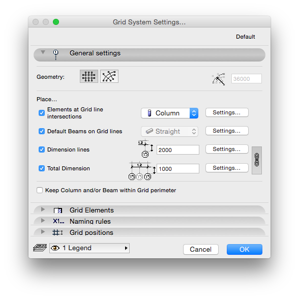


INFO > There is an additional option to select “Keep Column and/or Beam within Grid perimeter”. By default columns are placed with their centres at the intersection of two grid lines. Take care when selecting this option, as the columns along the outermost grid lines will now be placed on the inside of the grid line, in other words their centres will now be off-grid.
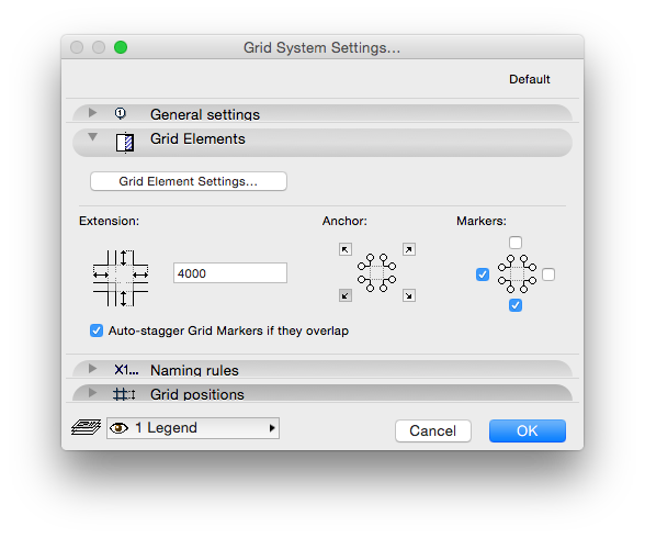
4. The Grid Elements tab is where you set up your Grid as described earlier. Select the Grid Elements Setting and the palette will open automatically. Here too is where you set the anchor point for your Grid System, as well as the extensions of the grid lines (in other words the placement of the Marker bubbles in relation the the last placed grid line). Choose whether you require markers at one or both ends of the line.
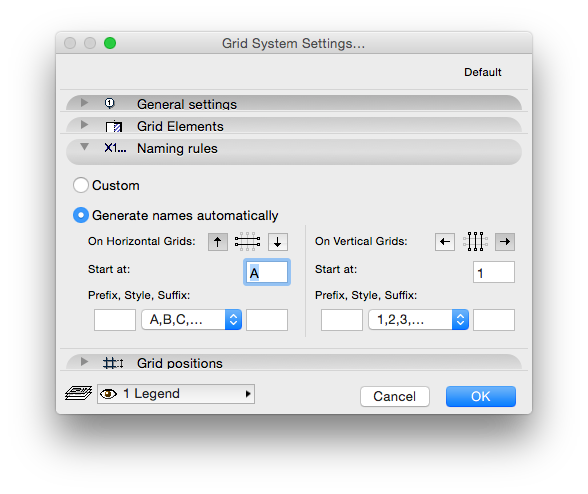
5. In the Naming Rules tab, set the numbering system you wish to use for both the horizontal and vertical grids (orthogonal grid system), or circular and radial grids (radial grid system). There is also the option to set these to a customised naming system.
6. Set the spacing, or intervals of the grid lines in the Grid positions tab. These can be spaced at regular intervals or vary according to the specific requirements of your project. You can also add or subtract a grid line between and two already placed, but as previously mentioned, beware that you do not change the grid set-out dimensions once you have issued your drawing. Only use this function if you are still in the design phase and/or are still setting up your grid.
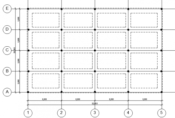
7. Place your grid in your plan view. Remember, as always, to check that you have the correct story for placement selected. The selections you made when setting your grid lines will determine if the grid is to display on one or all stories, as well as whether or not it shows up in section and elevation windows.
Click on your workspace. A ghost image of the Grid System will be displayed.
Drag your mouse in the direction of the horizontal (or angled, should your grid system not be orthogonal) grid line. Remember to hold down the Shift key to lock the horizontal! Click again and the grid system will be placed in your view, showing the selected structural elements (columns and beams).
macinteract Pty. Ltd. | ABN 44 155 154 653 | terms and legal. | © 2026