B3-1
Create and Edit Stairs
CAUTION > This stairs tutorial is relevant for Archicad 20 and earlier.
Introduction
It is critical to get stairs correct, not just in terms of their creation and placement with Archicad, but also in terms of construction. Ensure that the team member ideally with both the most construction knowledge as well as Archicad skill creates the stairs in your project, paying attention to, at the very least, minimum standards and compliances. Since most construction documentation packages have a drawing set specifically assigned to stairs, typically drawn at a larger scale and with additional detail and annotation to what would be placed in your working model, ensure that an appropriate level of detail for 2D vs 3D is applied.
It is important to create stairs with sufficient tolerance (!) early on in a project, before a Development Application if possible, as it is often difficult to rectify stairs and their adjoining core walls after the fact due to subsequent area constraints. This is particularly problematic when insufficient risers are allocated, thus the plan area is too small. It is wise to allow for additional width and length than not enough. Although there are a number of pre-made stairs for use within Archicad, in many projects stairs become quite specific, and as a result new project specific stairs need to be created.
The Stair Tool
Where to find: TOOLBOX
Use this to: Create stairs from the predefined types in your library.
There is the familiar layout to what we have seen in the door and windows tools, with the difference that you will need to specify dimensions in the parameters tab. The custom settings tab primarily relates to presentation.
Again, consider how much detail you need to include to be able generate a diagrammatic representation of a stair in plan, section and elevation. For this, also consider the scale of the drawings, i.e. a drawing at 1:100 will not benefit from detailed stairs that contain nosing, rounded steps, etc. Also, with large projects, having a large number of very detailed stairs in your model will impede the performance of your computer.
Stairmaker
Every SketchUp template contains a set of predefined settings for scene and units of measurement. By default, the ‘Welcome to SketchUp’ dialog box will pop up when you open SketchUp, where you can select the right template for your design.
We recommend to start with the Architectural Design – Millimetres Template if you intend to use SketchUp for architectural projects.The benefits of using Stairmaker versus the Stair Tool are as follows:
1. Additional available stair types,
2. More intuitive graphical interface,
3. (Specifically for larger projects:) since it creates a new library object you will only need to edit that library object for all placed instances to change.
4. Easier to keep track of variants as they are uniquely named objects and as a result of that easier to schedule.
It is highly recommended that you start by working out your stair on a piece of paper before opening stairmaker to identify:
1. height and width,
2. tread and riser numbers,
3. handrail location(s).
From this sketch perform a quick standards and codes compliance check.
Where to find: Design > Design Extras > Stairmaker or from within the Stair Default Settings > Create Stair.
Use this to: Create a specific stair as a new library part.
New library parts get added to the embedded library (i.e. all new stairs will need to be moved manually to the project library on the BIM server) unless you select Save as…
TIP > Identify one team member in charge of creating Stairs through Stairmaker, to give stairs a consistent setup. Also, other team members don’t have to worry about all the settings and only need to place them where necessary.
Name stairs according to a parameter such as height. For example, PROJ#_Stair type_Height. Beware of including the location of the stair in its name as the same stair could be used in multiple locations, especially in complex buildings.
How to create a Stair (Using Stairmaker)
1. Open the Stair Settings (Activate the Stair Tool and COMMAND + T)
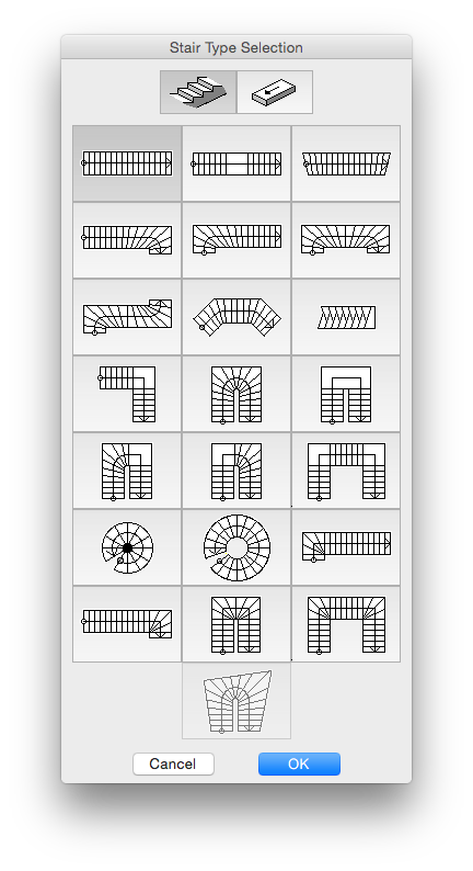
2. In the Preview and Positioning panel select “Create Stair” and the following window will appear: See Image 1
3. Select the type of stair you wish to create. For this example we will use a typical U-Return with Landing.
4. Go OK. This opens the main settings dialogue window: Image 2
5. Image 3
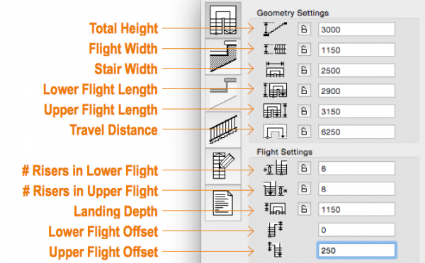
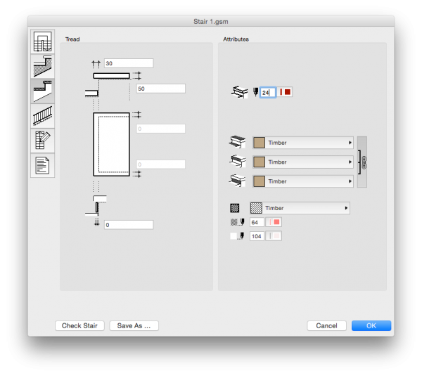
Activate the Geometry Settings tab and input the relevant settings. This image helps clarify the settings: Image 4
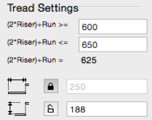
6. Set the Tread Depth and Riser Height. Should your tread have a fixed dimension of, say, 250 mm (typical minimum for a fire stair), it is recommended to lock this parameter once it has been set, to prevent it from changing when other parameters are modified. Ensure the maximum riser height is not exceeded. Check the relevant standards and add additional treads if needed.


INFO > Archicad has an inbuilt formula / compliant range for the ratio of treads to risers, i.e. (2*Riser)+Run, and will alert you should the properties you set not fall within the allowed range. (This can be manipulated, but do not attempt this unless you know what you are doing!)
AC-B49
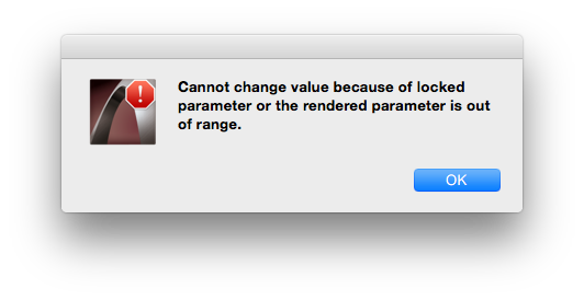
TIP > Only lock a parameter if it has a critical dimension. Locking parameters as you go prevents others from being set, and the following error message may appear: See Image
Remember it is not necessary to lock everything, just that which specifically must retain its dimension.
If later adjustments are necessary, strictly work through the parameters from top to bottom, since occasionally even unlocked parameters do not update. Keep in mind, however, that you may need to check your risers and treads for compliance as you go, as these are often the first thing Archicad chooses to edit to meet any new criteria you input.You may need to unlock all the parameters in order to edit a stair.
Select whether the top tread of your flight stops at or below the landing. Typically, “Top tread below the floor level” is the best option to choose.
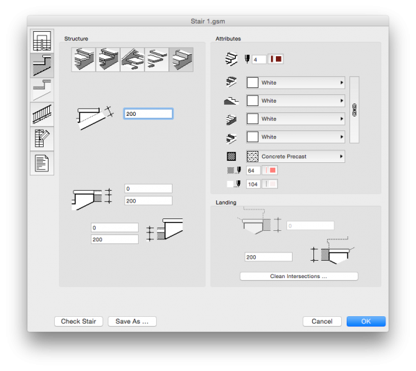
7. Activate the Structure and Landing Settings tab, and input the following:
7.1. the stair structure. (In this example we have chosen a simple concrete stair).
7.2. set the thickness of the stair slab, and input the top and bottom floor slab thicknesses. Ensure this is in accordance with your structural information.
7.3. assign a suitable 3D outline pen.
7.4. select surface materials.
7.5. select a cut fill and its associated pens.
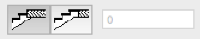
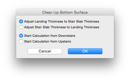
8. “Clean Intersections” brings up a palette where you can select by which means the bottom surface intersects with the floor slab. Typically you can ignore this function, as it is set correctly by default to “Adjust Landing Slab to Stair Slab Thickness”. Don’t be tempted to select “Adjust Stair Slab to Landing Thickness”, as this will have undesired consequences in that the stair slab will become very thin.
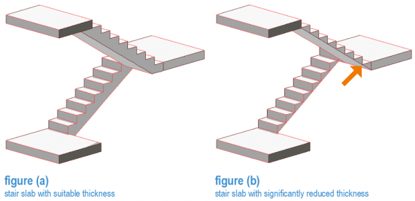
This can be demonstrated as follows in Images 4 and 5
“Adjust Landing Slab to Stair Slab Thickness” as in figure (a): stair appears as it should be. “Adjust Stair Slab to Landing Thickness” as in figure (b): it is clear that the stair no longer works correctly. (In this case it reduced the stair slab thickness to just 10mm!)
9. Activate the Tread Settings tab, should you have selected a stair with treads. This could be in the form of a floor finish on top of, say, a concrete stair, or alternatively a lightweight type stair.
10. Activate the Railing Settings tab. In this panel you will need to set the following:
10.1 type and location of your railing. You can select either
10.1.1 uniform, where your settings will apply to all sides of the stair;
10.1.2 define by side (inside rail / outside rail) or
10.1.3 individual segment.
In most cases, however, a simple bar type rail should suffice for general modelling.


TIP > USE the Rail Icon that appears when you hold your mouse over the rail in the preview window, to select and input the rail settings for options (i) and (ii) above.
10.2 Rail location in relation to the stair. In other words, whether it is contained within the stair or fixed to the outside.
10.3 The offset.
This is calculated to the centre of your rail so take care that you meet and codes or standards regarding offsets from walls, clear width of stair etc.
10.4 The height of the rail. Calculated as in (c) above.
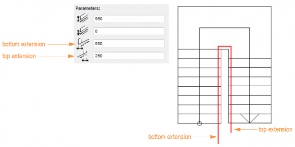
10.5 Bottom and top extensions. Particularly important for the first and last flights of a stair to comply with access and egress standards.
10.6 Additional parameters such as dimensions of rail and building material.
10.7 Should you select a rail type with posts, input the settings in the bottom or the right hand panel. You will also need to set any additional parameters related to the posts on the bottom left..
10.8 For additional information regarding rails, refer to the Handrails chapter.
11. Activate the Symbol Settings tab. This is where you will set the 2D display properties for your stair in plan.
11.1 select a suitable plan symbol. (Consider the display in relation to story sensitivity.)
11.2 set the representation for the walking line and posts (if applicable).
11.3 in the right hand panel, select the attributes for your plan display (pen colours, line types etc…). Any attributes which you do not require in your plan view can simply be set to “Off”.
12. AC-B60
The Listing Settings tab lists all the properties of the stair should you choose to schedule it and its components.
13. Check that your stair works by clicking “Check Stair”.


INFO > This obviously does not check for compliance with your local standards, codes etc!. It is purely checking for scripting errors which may corrupt the generation of your stair object.
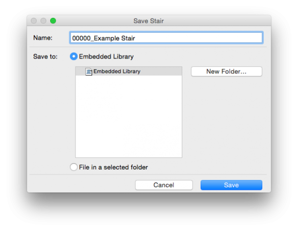
14. Save your stair and name according to your office naming protocols. By default stairs will be added to the Embedded Library.

TIP > Name stairs according to their type and floor to floor height rather than by location, enabling the same stair to be used multiple times in your project. e.g. Project#_ReturnStair_3000H.
You are now able to place the stair in your drawing. You are able to change or revise many of the parameters after the stair has been created, by selecting it and activating its settings (COMMAND + T).
Be aware, however, that you are not able to edit the stair’s structure here. In order to do this, you have to select “Edit Stair” in the Preview and Positioning panel, which will return you to the Stairmaker window.
How to Edit a Stair
Editing of stairs needs to be managed carefully. This is particularly important when editing a stair which has been placed in multiple locations. To edit a stair, select it and open its settings, and click “Edit Stair”.
Take care that, in the event that only one instance of a particular stair type requires editing, that you don’t accidentally overwrite them in all placed instances. Archicad warns you before you proceed. Ensure you select only “Selected” stair in this instance.
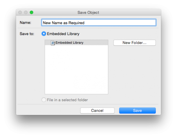
Archicad will prompt you to assign a new name to this edited stair. Name this new stair in keeping with the other stairs in your project.
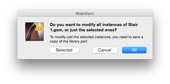
INFO > Should you wish to edit all placed instances of a particular stair type, select “All”. Archicad will then return you to the stair creation palette where you can make the required changes.
Stairs and Libraries
As mentioned earlier, unless you select “Save As” at the time of naming the stair and at that point select your Project Library, by default, new Stairs get added to the Embedded Library, and will need to be moved manually to the project library on the BIM server.
When using Teamwork, save stairs to the Embedded Library, where they will remain for the duration that they are being worked on. Ensure that you frequently save these stairs into your Project Library on your server. This then eventually gets refreshed to the BIM Server, and at that stage your stairs should get removed from the Embedded Library.
For a detailed workflow on how to do this please refer to chapter “How to set up your project” paragraph “Libraries”.
TIP > In Teamwork projects, when updating the Library on the BIM Server, to ensure that all team members actually received the updated library, it may be necessary for users to leave the project, delete the local library via the Teamwork > Project > Local Data Manager and subsequently joining the Teamwork Project once more.
Handrails
You can choose to display handrails on your floor plans or not, depending on the level of detail you are modelling to. Remember that the display of handrails in plan is scale dependent. However, because of factors such as Archicad’s inability to continue a handrail round a corner, or from one stair to the next in multi-story stairs, it is sometimes easier to draw a simple handrail in plan by means of fills. This can be drawn either over the top of the automated handrail display, or instead of it. Remember to tag the fill according to your legend and place it on the appropriate layer.
When creating your Stairmaker stair, although there are multiple options to choose from regarding handrail type or style, since detailed stair drawings are often drawn at a larger scale and sometimes even become 2D details, the simplest and easiest one to select is usually “Simple Bar”. In addition, consider the time spent in setting the selected handrail’s properties for multiple stairs in a project and determine whether or not the effort is worth it.
Handrail Extensions.
Further to the information contained in Step 10 in the previous chapter, How to Create a stair (using Stairmaker), there is additional information which is sometimes needed for your project.
In accordance with the Australian Standards, handrail extensions are required at the top and bottom of stairs in order to achieve compliance for access and egress. (These handrail extensions may vary depending on where you are located, so ensure you check the relevant Codes and Standards in your area).
INFO > For multi-story stairs, only the topmost flight in your stair requires a top extension, and the lowest, a bottom extension. These are not required on every level.
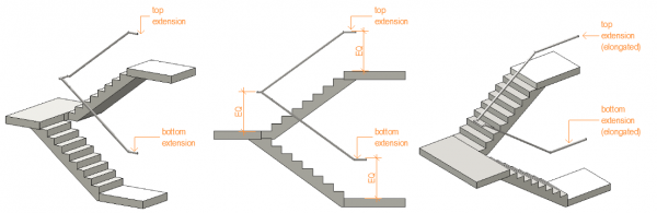
These are simple to set up in Stairmaker and can be done at the time of creating your stair, and can be found in the Railing Settings Tab. What these extensions look like is seen most clearly in perspective view (figure (a)) or side elevation (figure (b)): last image.
The overall height of the handrail needs to remain consistent. From a flight to a landing the handrail continues at an angle, until it reaches that point at which its height above the level of the landing is the same as it was above the stair flight, from then on it becomes horizontal.
In some parts of your building, handrails may be required to continue for an additional distance (figure (c) above). Should you wish to model these handrail extensions, simply adjust the length of the extension accordingly.

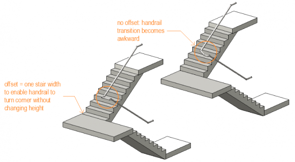
TIP > By offsetting the first tread of the second stair flight of a stair by the width of a typical tread (figure (d)), keep the transition of the handrail around the corner can easily maintain a consistent height:
Handrail terminations such as turndowns etc. tend to vary according to requirements so check any relevant codes and standards. These are rarely modelled in 3D however, but should you choose to do so, more detailed information can be found further on in this chapter.
Multi Story Stair Handrails
Unfortunately, Archicad does not yet have the means by which handrails can be set up to continue up multiple stories. Of course, should you have the time and inclination, you could well model these by means of Library Parts such as Tubes, Elbows and the like, but the effort is hardly worth it and editing becomes very tedious.
Typically, the only drawings which would require some indication of how handrails continue up several flights of stairs and around corners, are the Stair Detail Drawings. These are often to a larger scale than your model (1:50 or less often, 1:20), and are usually best drawn as a combination of 2D and 3D elements. From these drawings, details of any handrails or fixings can be drawn in 2D.
The simplest way of indicating continuous handrails up a multi-story stair is by means of fills or a combination of lines and arcs..
Workflow:
1. Model your stair using stairmaker, following the steps outlined above, selecting Simple Bar as your handrail style.
2. Ensure that where your stairs meet landings or slabs have clean intersections by ensuring continuity between Building Materials, Cut Fills, Line Weights and Layer Priorities.
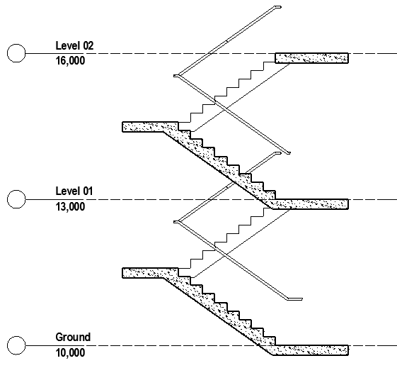
3. Generate the section, which will look something like figure (a)
4. You will notice that the handrails between the two flights do not meet. (figure (b)). You could, potentially, increase the affected top and bottom handrail extensions until they meet in the section view, but keep in mind what this will do to your plan (handrails will be too long).
5. Instead, using the Fill Tool, add in the missing pieces. Select either a solid fill with a white background, or background fill, with the window background selected, and ensure that the outline pen selected is the same as that of the handrails in elevation.
6. Draw the extension from the upper flight of one story to the lower one of the story above. Ensure that you maintain a consistent height above the floor level, as well as a consistent thickness of the handrail itself. (figure (c))
7. There may be a line displayed where the fill meets the handrail, but you can simply mask this out with a white pen if need be.
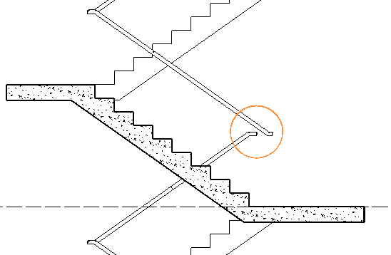

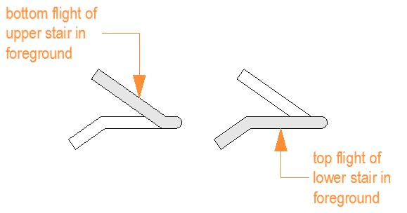
TIP > Take care when drawing the fills to ensure that the correct handrail sits in front. The handrail belonging to the stair flight closest to the viewer should always be in the foreground:
Occasionally, due to both time constraints, unavailability of suitable stair objects or unfamiliarity with the workings of Stairmaker, stairs can sometimes need to be drawn entirely in 2D line-work, and subsequently saved as a simple 2D Object for repeat placement in your plan views. Keep in mind, however, that should you choose to do this, you will have to draw them in section and elevation as well since you are unable to generate these views from your plan.
Customising Handrails
Occasionally, your stair handrail is an integral part of your design, and is highly customised. The best way to handle such situations, it to create your stair with no handrail included in the object. Once your handrail has been designed, either detail it all in 2D, (keeping in mind that each time you generate a different drawing of your stair the process will have to be repeated according to the view) or alternatively, you can build your handrails in 3D using the tools available in Archicad.
This does, however, require fairly advanced modelling skills, so ensure a suitable team member handles this task. Once modelled, these can then be saved as simple Library Parts for repeated placement in your model. Unless you have GDL Scripting knowledge, this is the simplest and easiest way to customise handrail objects.
Place these objects in your plan, and check (!) their placement in the elevation / section / 3D windows. Consider grouping them together with your stair object, so should the location of the stair change the handrails will move with it accordingly (if you have group mode activated).
macinteract Pty. Ltd. | ABN 44 155 154 653 | terms and legal. | © 2026