B3-2
Adding Supplementary 2D Information
Introduction
Archicad, although designed primarily to be used as a 3 Dimensional modelling program, still requires a certain level of 2D input, e.g. 2D information is typically required to annotate and dimension Plans, Sections and Elevations.
Adding Detail
Although it is possible to model to a great level of detail, it isn’t always wise to do so. Drawings will be slow to update, navigating the model will also become less responsive, and the time factor involved in correctly modelling to that level of detail can be significant. In addition this can be encumbered by the limitations of Archicad’s library, making adding 2D information the smarter option.
How and where you add 2D detail, depends on both the use as well as the source of the information. For example, one could place multiple detail markers in a model all of which contain 2D information, and with these compile a number of detail sheets. With proper cross-referencing, a clear overview of all drawn details, as with plans, sections and elevations, would then be listed in the Navigator.
Adding Annotation
Annotation relates to specific drawings, whether it be plans, elevations, details, etc. For that reason, it should only be added where relevant. The Layer structure of your file should be set up to accommodate annotation for various drawing types and scales, enabling you to generate as many drawings from your model as required.
For example, the same plan view in your model can be the source of both (a) a site plan at 1:500, as well as (b) a general arrangement plan at 1:100. Both drawings would require different forms of annotation on separate Layers, which are in turn controlled via Layer Combinations.
Worksheets
Every SketchUp template contains a set of predefined settings for scene and units of measurement. By default, the ‘Welcome to SketchUp’ dialog box will pop up when you open SketchUp, where you can select the right template for your design.
We recommend to start with the Architectural Design – Millimeters Template if you intend to use SketchUp for architectural projects.Worksheets can be used for: Placing of consultants’ information as external drawings.
File > External Content > Place External Drawing lets you place a DWG file without bringing in any file polluting attributes, provides you with a clean Trace & Reference which only contains the relevant information, and also saves you the hassle of controlling visibility via Layer Combinations had these drawings been placed in your plan view.
Quickly testing design options.
Legends
Typically legends are placed on multiple layouts, and under the motto of “draw it once”, making worksheets the obvious choice for placing legends. As noted below, additional 2D information on Layouts should be limited to only that which is absolutely necessary.
Enforcing company standards.
What not to do.
Do not treat layouts as drawings. The only additional 2D information permitted on Layouts should be directly related to the Title Block. This is because anything drawn on a Layout has no relation to either your model or scale. Do not simply add worksheets and detail sheets because you can.
This is for several reasons:
It is important to maintain an overview of what is in your file. A long list of worksheets makes navigation cumbersome, and it can be hard to find what you are after. The list should therefore be purged regularly.
Every worksheets adds a few MB’s to your overall file size. The bigger the file size, the more your computer’s performance will suffer.
Do not assign unclear names to worksheets and detail drawing sheets.
Maximum clarity needs to be maintained to aid with navigation, particularly on team projects. Avoid using dates and initials in the names where possible. Be descriptive enough without going overboard, e.g. use office standards such as a consultant code and drawing type (ID would be “E-001” and Name would be “Ground Floor Electrical”).
Autotext
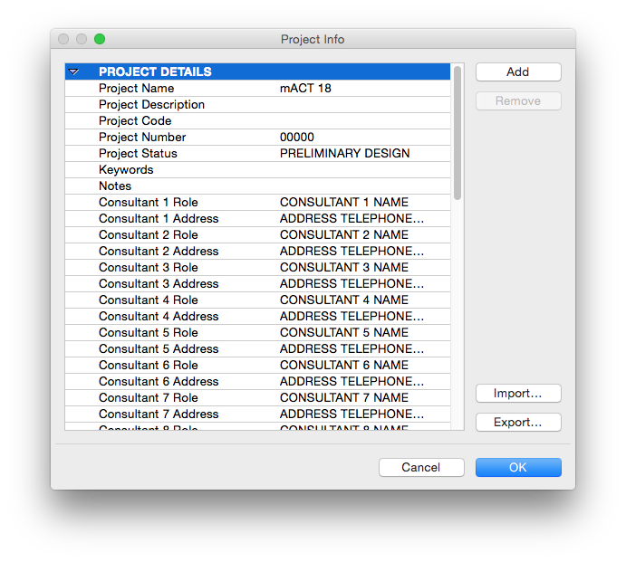
Autotext refers to items (data blocks) that are defined by Archicad and relate to Drawings, Layouts or the System (e.g. Layout ID, Drawing Name, Date / Time etc.), or are user defined in the Project Info.
Defining Autotext.
Where to find: Archicad > Project Preferences > Project Info
Any item added here will be available as a source for the Autotext.
INFO > The list itself can not be easily re-ordered, so have a plan for your template setup before you start editing it! Also, keep in mind that Autotext’s primary use is for general project information, to be displayed on title blocks.
TIP > Use the Export… function to save your Project Info as an XML file. This file can then be used either as a backup or it can be imported into any other Archicad file (particularly useful for large multiple-file projects).
Inserting Autotext.
1. Add or edit a text block.
2. In the pop up palette, click on the “A” icon:
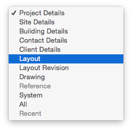
3. Define the category of Autotext, which will define which items are available to choose as autotext: Last image
4. Return to the Insert Autotext palette and choose the item you require.

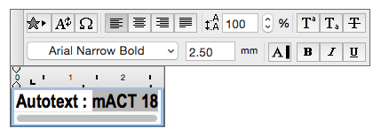
TIP > You can recognise Autotext by its grey background:
Bulk Edit Text.
Text (and Labels) occur on every drawing at all stages of a project; the level of information that they convey is what differs from one stage to the next. Frequently, the information contained within a Label or Text Block needs editing, for example if a material changes and all tags associated with that material need updating. The simplest and fastest way to do this is to use the “Search and Replace” function. Go Edit > Search & Replace Text…
Workflow: To define your search criteria, type in the relevant information within the pop up window, and click “Start Search”.
Archicad will then select all text that meet your criteria in your active drawing window (!), and give you a total number of placed instances. (You can scroll through this list and deselect as required.)
Go “Replace All”.
Should you wish to be more specific, for example if you wish to replace all Text as well as any Labels that contain the criteria you specified, click on “Filters” and a second window will open: Last Image
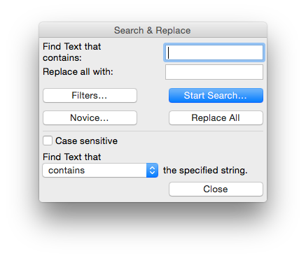
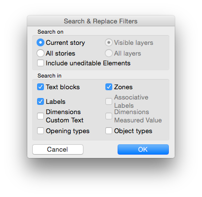
TIP > Should you wish to access the greyed out options in the figure above, select “Include un-editable Elements”. Additionally, you can Search & Replace text on either the current story or all stories.
INFO > Text placed in Hotlinks can not be edited anywhere else other than in the Hotlink source file.
Zone Stamps
Zone stamps are complex text blocks that form an integral part of a placed Zone. The properties that get listed in the Zone Stamp can be defined by choosing a Zone Stamp in Options > Element Attributes > Zone Categories :
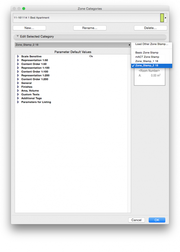
INFO > Zone Stamps need to be defined for every Zone Category. Coding your own Zone Stamp is possible , but requires advanced knowledge of GDL scripting.
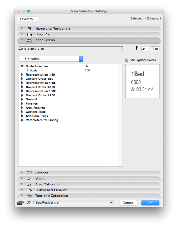
You can further control what gets displayed in the zone stamp in two ways:
Per individual Zone via the Zone Selection Settings window (select a Zone and COMMAND + T). You can adjust which information is displayed as well as how they display graphically.
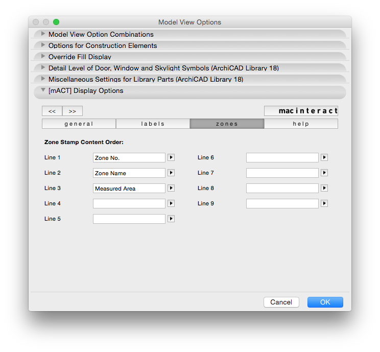
Globally through Model View Options.

INFO > Note that this requires gdl scripting or purchase of a third party software, such as our Smart Template or Masterscript’s Total Zone.
Dimensions
Where to find: Toolbox > Dimension Tool
Use this to: Dimension and set out your building(s). Dimensions occur on many drawing packages to varying degrees. They can be quite general during early project stages such as DA, typically just overall building dimensions and the like, whereas during the construction documentation and detailing stages they are an integral part of the drawings and are heavily relied upon. It is critical that dimensions are both accurate as well as legible. In this chapter we will explain how to set up a dimension style for your project as well as set up the project preferences.
Before you proceed with dimensioning your drawings, ensure that you set up a suitable dimension style in keeping with your office standards:
1. Open the Dimension Default Settings window in the Toolbox.
2. Select the Dimension Type.
2.1 Typically this will be the first tab along (Linear Method) for plan drawings.
2.2 The second tab, Cumulative Method, (also known as “Running Dimensions”) is used when dimensioning additive points along one dimension string. For example, when dimensioning heights in elevation referring to a base level, such as the relevant story (e.g. dimensioning shelve heights from a joinery unit).
2.3 The third tab, or Base-Line Method dimensions points as an offset from absolute zero, or x=0;y=0. This method is not commonly used in Australia, so you can safely ignore it.
2.4 The last tab is Level Dimensions, and are used in sections and elevations to annotate a level or elevation from your Project Zero, or from a Datum level such as AHD. These are usually noted as an RL.
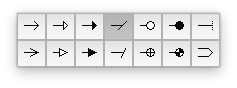
3. Select the Marker Type.
The angled “slash” is the most commonly used: Image 2
4. Ensure Static Dimension remains unchecked!
The reason for this is should you check this box, when your drawing changes and dimensioned elements move, the dimensions will not automatically update.
5. Select your Pens.
We recommend a heavier (relative to other pens used here) pen weight be attributed to the Marker.
6. Set the Witness Line type and length.
This is typically the third tab along, i.e. Custom Height. Avoid setting the Witness Line as any of the other options for the following reasons:
6.1 None: As a rule, Witness Lines or dimension “tails” should point to the element being dimensioned. This option does not have one at all.
6.2 Sized Height: As a rule, Witness Lines or dimension “tails” should point to the element being dimensioned. This option creates a Witness Line of equal length on either side of the Dimension Line and can create confusion, especially in busy drawings.
6.3 Dynamic Height: This will use a specific offset from the element being dimensioned and tends to create very long dimension “tails” which can obstruct other information in your drawing.
7. Select the font and its size based on your office standards.
8. Set the size of your Marker, and length of the Witness Line in the second tab; Marker and Witness Line Options.
We recommend keeping the Marker relatively small, as it can interfere with the dimension text if it gets too long, especially along shorter dimension lines where space is already minimal.
9. The next panel, Dimension Details includes options for:
9.1 Displaying opening heights of doors & windows (not commonly used so keep this unchecked)
9.2 Dimensioning wall and slab cores.
This option, although uncommon, is sometimes requested by particular builders during Construction Documentation, (for example dimensioning to the stud rather than the plasterboard in a stud wall), so we recommend setting this option to the requirements of your particular project.
10. Since Dimensions are typically not tagged, the last panel, namely Tags and Categories, can merely be ignored.
Setting up Project Preferences for Dimensions.
Where to find: Options > Project Preferences > Dimensions…
Use this to: Set up as an Office Standard or Project-wide.
Note that these settings are file specific, i.e. you will need to transfer these to other files manually if changes are necessary. Set this up as part of your Archicad Template.

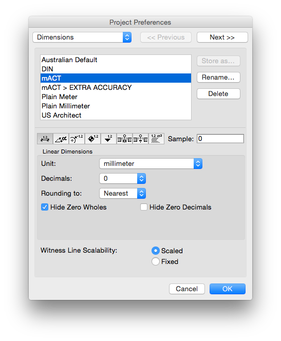
TIP > To facilitate accurate modelling we recommend adding an “extra accuracy” dimension preset. You can activate this through the Quick Options palette while checking your model and have the regular dimension preset as part of your Saved View.
macinteract Pty. Ltd. | ABN 44 155 154 653 | terms and legal. | © 2026