B3-3
Annotation
There are various approaches to annotating drawings, we find that applying the following simple principles enhance not only the clarity and thus the readability but also make it much easier to keep everything up-to-date.
1. only annotate non typical elements, i.e. deviations from the norm;
2. typical elements are clearly represented either by their graphic representation or via a legend;
3. do not use static dimension chains and associate them to the correct elements;
4. use data contained in elements, e.g. a wall code is embedded in the wall itself and read by an associated label (and not a static text label);
Labels and Dimension Hierarchy
Introduction
Drawings, typically, can not be issued to clients, builders or consultants without a certain level of annotation on them. Obviously the amount and specifics of this annotation will differ depending on the stage of the project as well as the drawing type, or package, being prepared. In addition to the various tools, such as the independent label, dimensions and text, there are a number of linked labels and tags available to you with which to annotate your drawing. In this chapter we discuss the various tools, labels and tags, and how best to use them.
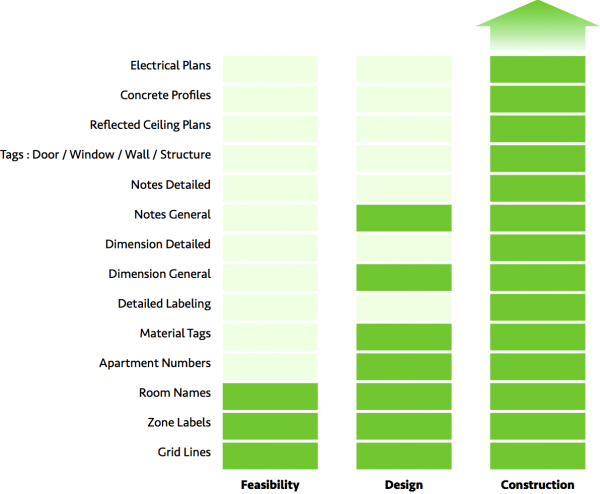
Typically, during the early stages of documentation, such as Feasibility or Development Application, the annotation is more general. It would include Room Names, General Notes, and possibly information indicating Solar and Ventilation compliance.
Once into Construction Documentation, additional and more detailed information is required, including Dimensions and various Tags and Labels, which in turn reference back to more detailed Schedules and Specifications. In addition, different Annotation is required on different drawing packages. For example, structural type information relating to Concrete etc. would be added to a Concrete Profile Drawing. Wall and finishes Labels, Door and Window Markers, etc. to a General Arrangement drawing. Dimensions are required on both.
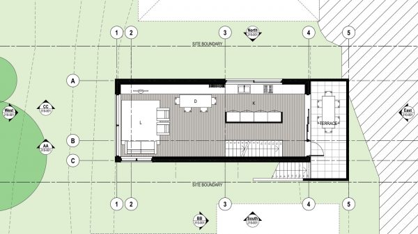
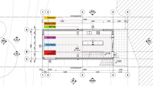
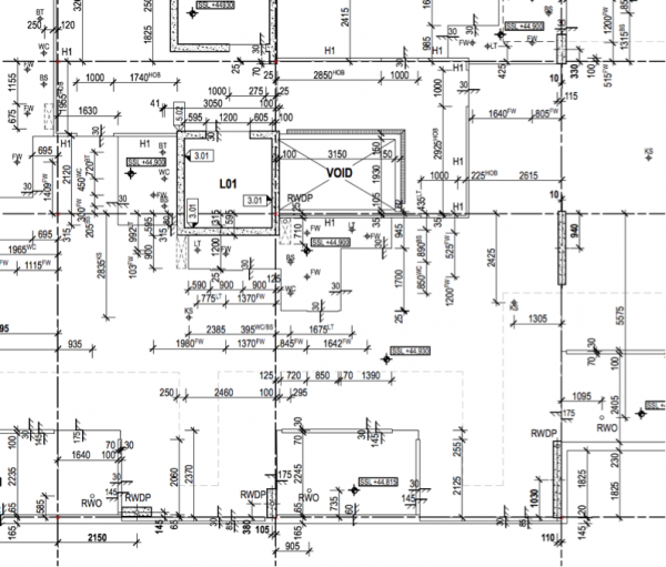
The following images show typical General Arrangement Plans for Development Application and Construction Documentation respectively, and notes the annotation typically found on this type of drawing: Image 2 and 3
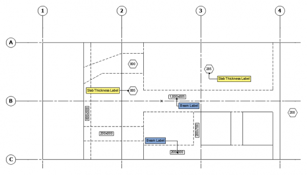
Image 4 shows the Annotation one would use during the modelling stage for what will become a Concrete Profile Plan.
INFO >
1. Ensure readability and clarity.
2. Be mindful of annotation clashing with other drawn elements.
3. Should you choose to use Scalable Text, be careful where and how it is placed, as its position could move as the drawing scale changes. Decide which of the 9 available nodes for text placement is suitable for each text box.
4. When placing text, double click and type. Do not draw a big box and type within it as this makes correct alignment all but impossible.
5. Consider whether text and annotation is aligned centrally, such as for room names and other relevant info, or left / right aligned when using the Label Tool with pointers.
6. Location of room names, if used across multiple drawing packages, should take into consideration things like location of light fittings in the RCP view and be placed in a consistent and suitable location across relevant drawings.
TIP > Never place annotation on the Archicad layer as anything placed on this layer will display on all drawings. Keep annotation layers for text and notes separate from those used for dimensioning.
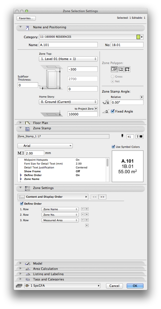
Zone Stamps
Where to find: Zone Stamps are part of placed Zones. The information the label displays can be controlled in the Zone Settings and be overridden by the Model View Options.
INFO > The default label for a zone is defined in Options > Element Attributes > Zone Categories…
Use this to: Zone Stamps are used right from the setup stage of a project and are one of the first forms of annotation placed. If placed correctly, they can remain in the project for the duration, in other words, right through the construction documentation stage.
Typically, the information you would show in this zone stamp could include:
1. The Gross Floor Area (GFA) or Net Lettable Area (NLA)
2. The Room Name or Space Name (eg. lobby)
3. The Floor Finish
4. The Building Number / Apartment Type
Floor Finishes
Floor finishes are typically placed by one of following means although there are several ways to annotate them.
Fills
Vectorial Hatching assigned as cover fill to a structural element, e.g. a slab.
Slab or Mesh (in case the modelled detail is required). Should you choose to use fills, these can be annotated by a tag linked to the fill ID. Ensure the location of the tag is placed so as not to interfere with other drawn elements within the space / room. Place the tag on a specific layer such as AnnoFinish (Annotation Finishes) which can be turned on or off as required.
Should you use Zones to designate individual spaces or rooms within your building, the Floor Finish can be added to the contents of the Zone Stamp. Ensure that the layer containing the Zones is turned on in all relevant layer combinations.
Of course you could simply add a second line of text indicating the floor finish to the Room Name text, however, keep in mind that should these room names be used in multiple drawing packages this may not be the best location.
Dimension & Dimension Labels
Where to find: Toolbox.
Use this to: There are a number of Dimension tools available in Archicad, these include…
1. Dimensions
2. Level Dimensions
3. Radial Dimensions
4. Angle Dimensions
The dimensioning process is ideally begun in the very early stages of a project and initially serves mainly as an incentive to model accurately from the outset. Therefore, in the feasibility stage of a project turn on Extra Accuracy where the dimension is set to display to 0.1 of a millimetre. In addition, attempt to model to a rounded off dimension such as 5 or 0, so as not to end up with odd dimensions. Place the dimensions on the correct layer from the beginning, and turn this off via layer combinations if so required.
TIP > When dimensioning e.g. apartment modules, ensure all dimensions are placed within the extent of the module boundary. For example, should the extent or boundary of an apartment module be defined by a polyline, ensure that all dimensions are placed within it, otherwise these dimensions could interfere with other drawing information directly adjacent. Also take care when placing dimensions to apartments whose orientation may rotate or flip as the text on the dimension may switch to the other side of the line. Place with sufficient space for either situation.
Dimensions
Where to Find: Toolbox: Double Click the icon or Document>Documenting Tools>Dimension and Command+T for the Settings.
Use this to: It is crucial that dimensions are placed accurately as well as thoroughly and show sufficient information in order for maximum clarity during the construction process. Almost every drawing package will have some level of dimensions associated with it, and depending on what type of drawing package it is, the information these dimensions highlight may vary.
1. Ensure dimensions are associative and do not use static dimensions, otherwise should something be edited, dimensions will not update accordingly.
2. Never copy and paste dimensions by themselves as they become static by doing so. (Association remains intact if you copy dimensions along with their associated elements.)
3. Dimensions need to be clear and consistent, and of course, readable. Ensure that you dimension to or from a grid line, provide overall dimensions, and additional dimensions for an area that is particularly detailed.
4. Avoid dimensioning numerous different elements along the same dimension string as this may become confusing. Instead, rather use several strings of dimensions evenly spaced from one another. Also consider naming these dimension strings for clarity, e.g. “Facade Openings”.
5. Those referring to the external walls of the building such as overall dimensions, openings like doors and windows, changes in direction etc should ideally all be placed outside the building envelope.
6. Internal dimensions for apartment modules (for example) can be placed within the module itself as described above.
7. Make use of superscript, particularly with concrete profile drawings, as these can become very full drawings displaying a lot of information. Use this superscript to identify the different hydraulic penetrations, e.g. floor wastes (FW), toilet pans (WC) etc. This will ensure clarity as to what is being dimensioned and minimise errors and confusion on site.
8. When dimensioning internal spaces, identify a room or other part of the plan where there is potentially some margin for variation in terms of size and dimension only to either side of this space.
9. Ensure dimensions have Witness Lines or tails which point in the direction of what is being dimensioned.
10. Never place dimensions on a PMK or worksheet and place this in your drawing as accuracy is compromised, and dimensions will not update automatically.
INFO > For specific drawings such as concrete profiles, which require the Structure Display in the View Settings to display as “Core Only” due to the use of composite wall types, ensure that the dimensioning process is only begun after the setting has been activated. Should you dimension whilst “Entire Model” is activated and then change the setting afterwards, dimensions will no longer display. (Dimensions placed whilst in Core Only view do, however, display in Entire Model view.)
Level Dimensions
Where to Find: Toolbox: Double Click the icon or Document>Documenting Tools>Level Dimension and Command+T for the Settings.
Use this to: Level dimensions are used to annotate Structural Slab Level (SSL), Finished FLoor Level (FFL), Relative Level (RL) or Ground Level (GL / FGL) etc. These can be linked to the concrete slab, but tend to relocate themselves on the drawing should the shape of the slab change for any reason or if it is split. Unlinked Level Markers are easier to locate, however, they will need to be manually updated should any levels change.

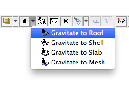
TIP > Take note of the option to Gravitate to….. in the Standard Toolbar (Window>Toolbars>Standard). This way your spot levels associate to the element it is gravitating to.
Graphical Display Settings
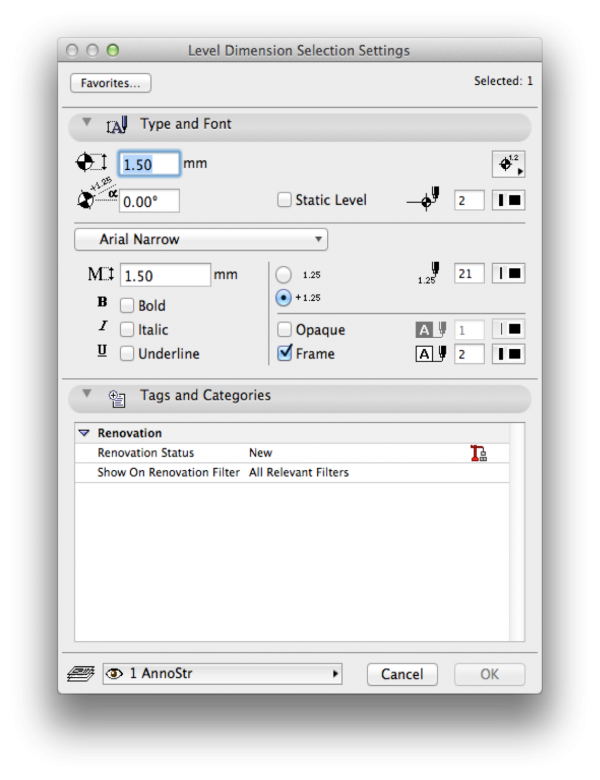
It is recommended to set the display of Level Markers such that they can be easily differentiated between the different types of levels indicated, especially on drawings such as General Arrangement drawings, where all four situations (SSL, FFL…etc) could occur on the same drawing.
You can change the graphical representation for marker and text separately. The default dimension settings will bring up a window where you can define marker, font, font-size and pens:
However once your level dimension is placed you can also select its text element (Node in bottom left corner of the text) and then press Command+T for the following text settings:
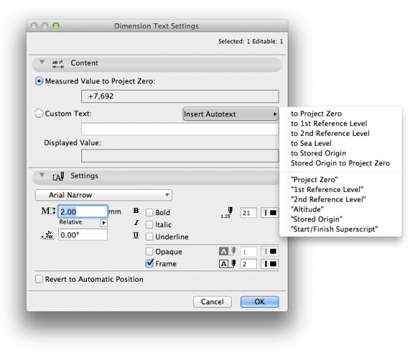
TIP > You can type ^ (on an Apple Keyboard this is Shift + 6) as a shortcut to start typing in superscript.
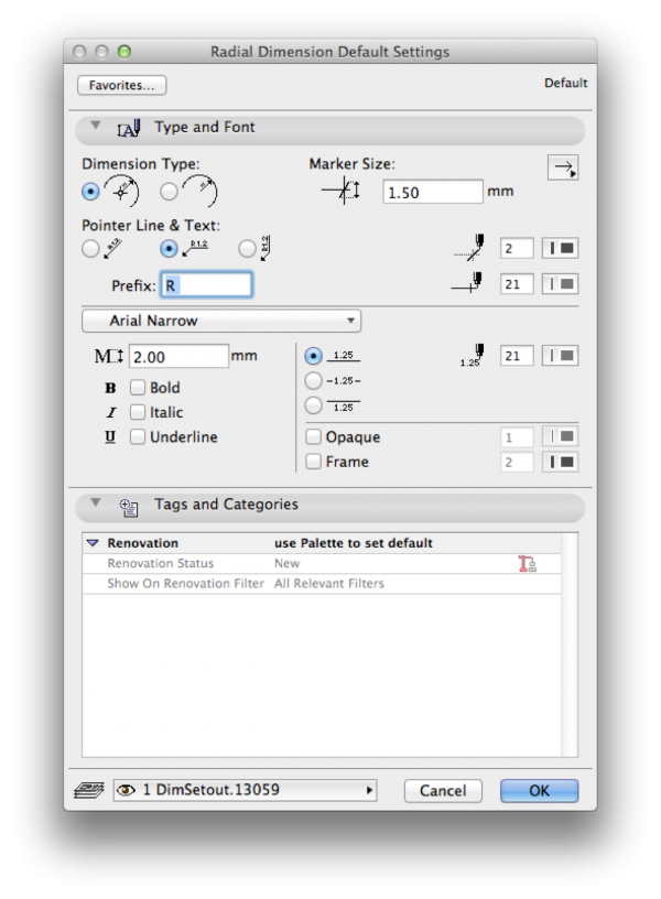
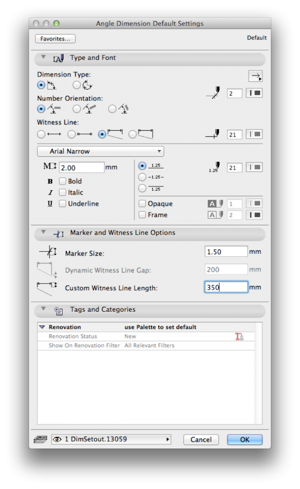
Radial Dimensions & Angle Dimensions.
Although not as commonly used, ensure settings such as pen colours, line weights and font size are consistent with other dimension styles. Set up and use Favourites for consistent graphical display.
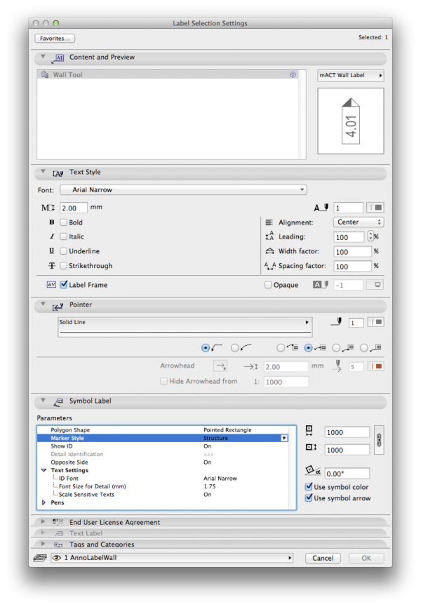
Wall Tags/Labels
Where to find: You can set defaults per Element type by double clicking the Label icon in the Toolbox.
Use this to: Wall tags are a critical part of Construction Documentation annotation. They relate back to the Wall Schedule and it is critical that they are correct, in order to identify the correct wall type, composition, fire rating etc.
TIP > As tagging wall types, particularly with discontinuous wall systems can be a lengthy process, when drawing any wall, even in early stages of documentation (even before they are needed on the drawing), assign the Wall Type as outlined in your wall schedule to the ID (or other Property fields) of each wall. This is what the tag will read when you are ready to begin the tagging process.
Ideally all of your walls will have been created as composites, with their type noted somewhere in the name of the composite. This will allow easy, en masse tag assignment when eventually required, by means of automated tagging. Assign a suitable tag object (see Smart Template examples below) which can have their display changed to identify whether a wall is structural, a core, lining etc.
Check for overlapping with other annotation on the drawing. Flip the tag to the opposite side of the wall, and delete superfluous tags as required. Ensure tags are on a layer which can be turned on or off as required, in other words, not on the same layer as the wall itself.


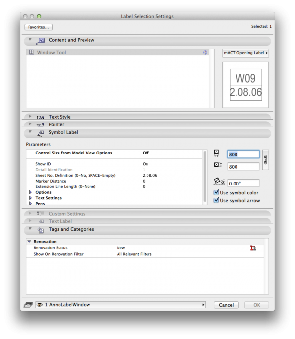
Window Tags/Labels
As with wall tags, the window tags read the required information from the ID (or other Property fields) of the windows, for the purposes of scheduling. Ensure that this ID is the same for all identical windows.

INFO > Should you choose to display window tags in elevation as well as plan view, the window object tag needs to be separately enabled in each elevation.
Door Tags/Labels
Door tags are assigned, as with windows, for the purposes of scheduling, and are best linked to the object Property fields. Door Labels can be assigned early in a project and placed on a layer that is turned off until required.
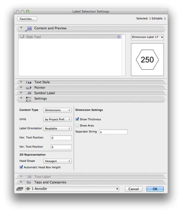
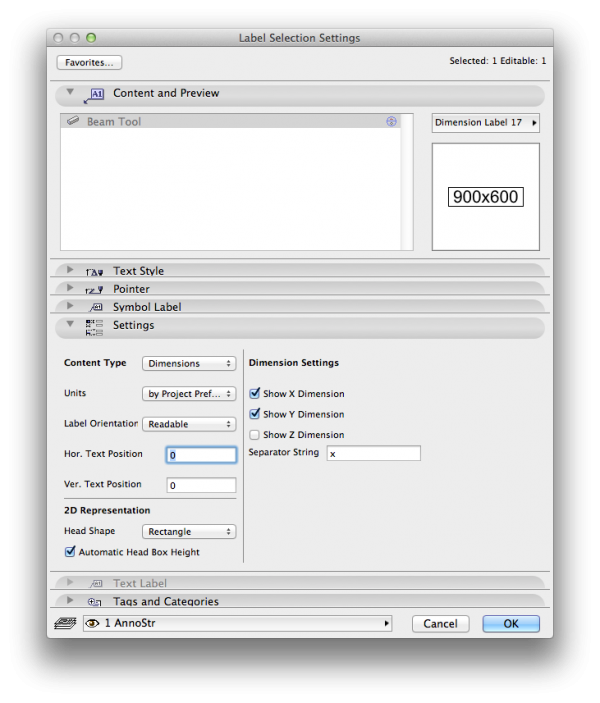
Structure Tags
In brief, select a suitable tag depending on what structural element you are identifying, e.g. choose a Hexagonal tag for concrete which identifies its thickness, a boxed rectangle identifying width & depth for beams, etc. As structure is typically labelled or annotated by the Structural Engineer, we suggest creating a layer called Z_CheckDimStr and place structural tags you require for coordination there. Turn layer on whilst editing and updating only.
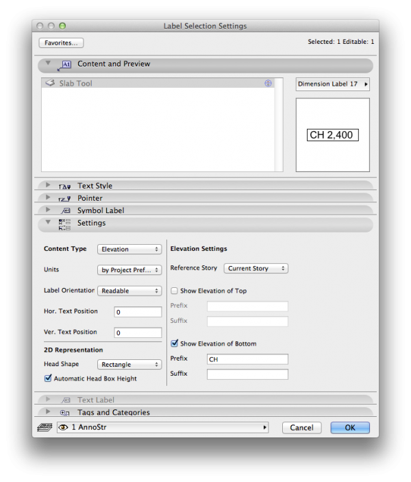
RCP Labels
As with Tagging Structure (above), refer for more detail regarding the process of annotating RCP’s in the chapter How to draw RCP’s and How to draw Concrete Profiles.
A dimension label can be associated with the underside of an element drawn to represent a ceiling (like a slab, for example) to show its clearance or ceiling height.
macinteract Pty. Ltd. | ABN 44 155 154 653 | terms and legal. | © 2026