


macinteract Pty. Ltd. | ABN 44 155 154 653 | terms and legal. | © 2026
During the DA stage of a project, Elevations and Sections are far more presentation based than during Documentation. Make use of elements such as 2D Library parts like trees, vehicles, people etc. to embellish your drawings. Place these on a layer such as “Ent2D” (Entourage 2D), which can be turned off or deleted along with all its content before proceeding with the Documentation stage.
DA Sections are often cut through less than perfect 3D models and thus require a certain degree of masking. Mask out larger areas with a solid white fill, and unwanted lines with white lines. Place on a designated layer such as “MaskingWhite”. Once beyond the DA stage and into Construction Documentation, the adjustments to elevation and section settings are relatively minor. Layer combinations get updated to now exclude the entourage layers described above. Additionally any masking and decorative fills (e.g. background sky) are now deleted, or their corresponding layers are turned off.
Depending on the level of information that is to be provided in your construction documentation set, elevations sometimes remain in colour and are issued as such. Typically, however, this is usually only done for small projects, or those whose facades are quite complicated in terms of materials and this is most easily displayed by representing the actual finishes / materials in the elevational views. Sections for CD are generally black and white, and display the cut fills for structural elements as in the plans.
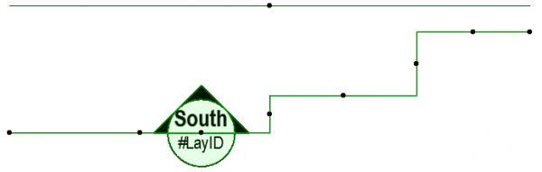
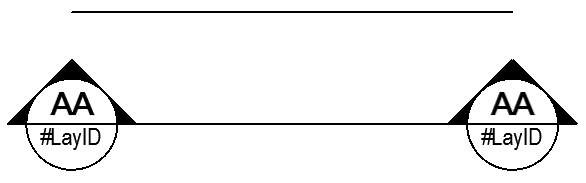
The text settings determine what appears in the marker head, i.e.. the name of the Elevation as well as the location thereof in your Layout Book (the sheet number). In your model file, until the Elevation drawing is placed on a sheet, this will usually be undefined (#LayID), but thereafter the sheet number will appear. The Marker Heads of both elevation and section lines are typically only set to display in this manner during the CD stage, to maximise clarity regarding cross-referencing of drawings.
INFO > Remember to change the MVO and update the view sets accordingly when transitioning elevations and sections between project stages.
Using a white pen to mask will allow you to easily visually check where a masking fill is placed if you have the following option turned on: Archicad > Work Environment > On Screen Options > Automatic Pen Colour Visibility Adjustments for Model Views. If you however want to block out the masked part when exporting a DWG then you should use a Background Fill using pen -1.
The difference between an Elevation and a Section marker is minimal. The main difference being that an elevation marker can not have a zero depth and also can not be staggered, whereas a section marker can.
Where to find: Toolbox or Document > Documenting Tools > Elevation
Use this to: Place an Elevation Marker.
Ideally, check the marker’s settings before you place it. Pay specific attention to the following:
General:
Type: Which type of marker you are placing and its subsequent Reference ID and Name. Typically You would place a “Source Marker”, which you would link to the first placed drawing of the viewpoint. This means that the text in the marker head will display the drawing number of the layout sheet the elevation is placed on automatically once it has been placed
Status: Manual Rebuild-model. Typically, having control over when a drawing updates is recommended. Having this on manual also results in less time waiting for a drawing to open as it doesn’t need to be rebuilt first.
Range: Unless you specifically want to hide part of your model from the generated elevation, keep the Horizontal Range on infinite.
TIP > In order to adjust the the range of the marker you need to display it first.
Go View > On-Screen View Options > Marker Range.
Adjusting the Vertical Range can be useful should you wish to limit your drawing to only a portion of your model. That could be a detail of a facade, or simply a view that limits the full extent of your ground mesh. (This is more a practical setting than adjusting the drawing frame of a drawing placed on a layout, which in essence, would achieve the same result). Zoom extents would in this case, capture less of the modelled info, and negate the need to resize the drawing frame of drawings placed on a layout.
INFO > Keeping the entered dimensions relative to Project Zero is the safest choice, as the Level is unlikely to change when you adjust storey heights.
Marker: Choose a marker object from the available libraries (in keeping with your office standards).
Select the Font type and size (in keeping with your office standards).
Set the size of the marker, and choose a Marker Style.
Set the various pen colours (in keeping with your office template).
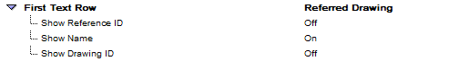
As described above, the text which displays in the marker head (name and sheet number) is now set as follows:
Set Show Name to “On”, and both ID’s to “Off”. (You want the information in the Marker Head to be as simple and clear as possible).
TIP > In order to adjust the the range of the marker you need to display it.
Go View > On-Screen View Options > Marker Range.
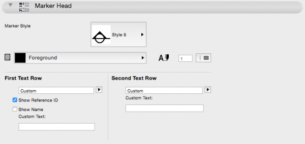
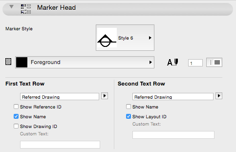
Marker Head: Choose a Marker Style (in keeping with your office template).
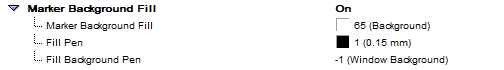
Set the Pen Colour as well as Fill Type for the Marker. (Note that Fill Type is only applicable for some Marker styles.)
Also located here is a summary of the text settings for the First and Second Text Rows in your marker bubble. They can be set / edited here as well.
Model Display:
In this section you control how your model will be displayed. When you adjust Elevation Settings from design to construction stage, this section is where you would concentrate your efforts:
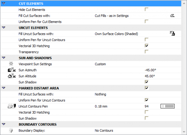
Cut Elements.
Adjust the way cut elements are displayed. For example, you can assign everything that is cut to use the same fill and the same pen. Useful if you want a more diagrammatic representation of your model. For example, for DA type drawings, set Cut Elements to Uniform Pen, and for Construction drawings, use “as in Settings” which will display the structure in the same way that the Plan view does..
Uncut Elements.
Adjust the way all uncut elements are displayed. For example if you want a very clean, line only drawing without colour, set the following options:
– Fill Uncut Surfaces with > Uniform Pen Colour – Uncut Surfaces Pen > (-1) Window Background
– Set Uncut Contours Pen as desired
– Set Vectorial 3D Hatching as required
– Un-tick Transparency so whatever is behind transparent element does not show.
Sun and Shadows.
The most consistent way is to leave this option on “Custom”. Even though this might not reflect reality, your drawing will read better graphically. You can also adjust the sun azimuth and altitude for each elevation, which is not an easy option if you choose to use “As in 3D Window”.
Tick “Sun Shadow” to turn on the display of shadow, and choose the associated pen and fill type.
INFO > If you are using the Marked Distance Area as described next, you can override the pen and fill type for shadows for the distant range of the Elevation.
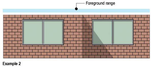
Marked Distant Area.
The pens and fills defined here will override the pens and fills that have been defined per drawn element, and will only be applied to the distant range of your elevation.
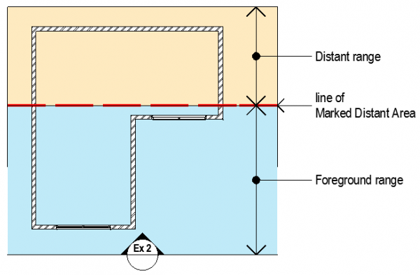
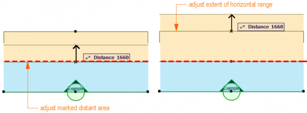
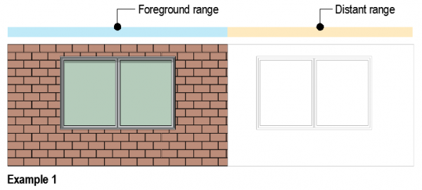
INFO > Within the horizontal range you can have two zones or ranges in your elevation to which you can assign separate model display settings. For example, the range closest to the marker (foreground range) could be kept in colour, or even set to display the elements’ materials, and the pens for the range further away (distant range) can be overridden so that anything captured within that range displays in (for example) grey outline. This is an easy way to add graphical depth to your drawing. The setting to turn this option on is in Elevation Default Settings > Model Display tab. Tick Marked Distance Area and adjust pens to suit. The two examples below show the effects obtained as a result of moving the line of Marked Distant Area:
Boundary Contours.
Adjust the contours of elements at the extents of your elevation marker. For example, the ground mesh might extend beyond the extent of your elevation marker. (The ground mesh might be 100 meters wide and the elevation marker only 50 meters.) The settings here allow you to override what those lines at the extremities look like. Choose “No Contours” to indicate that the element continues beyond what is shown on the drawing.
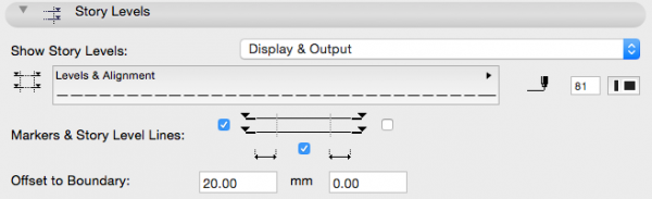
Story Levels: Unless you defined the extents (i.e. width of marker and range) of your Elevation Marker properly, the in-built display of story levels and names isn’t likely to show exactly where you would want them in your drawing. In this tab you can define if the Story Levels are Off, For Display Only or also to be printed.
INFO > You can globally (!) turn on / off Story Level Lines and Story Markers by checking / unchecking the boxes in the Story Settings dialogue (COMMAND + 7).
TIP > Typically you would select one side only to display the story level markers. Select which is best graphically for your elevation, and provide an offset from the boundary (of the contained elevation) to ensure that the associated text does not interfere with the drawing.
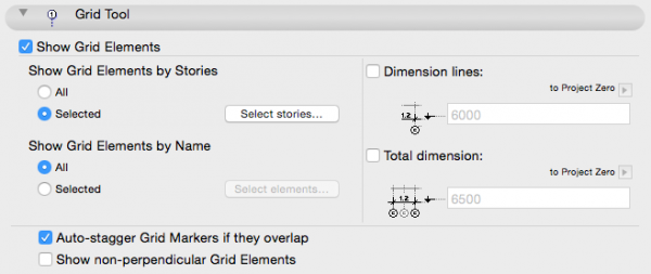
Grid Tool: This mainly defines whether you want to show or hide grid lines and their associated dimensions that you have drawn using the Grid Tool or Grid System.
TIP > To adjust the extent of your grid lines you will have to edit the individual grid line settings themselves, which will then be applied globally to all elevations and sections.
Check the option to Show Grid Elements.
Should the Grid lines be drawn in a Module file which is subsequently placed in your working file, choose “Selected” stories rather than “All” to avoid duplication of grid elements. Select the relevant story in the Select stories… tab.
Select “Show Grid Elements by Name”.
(You want all relevant grids displayed in your view).
Uncheck Dimension lines since these are typically only set out in your plan.
TIP > Save your settings as a favourite for use throughout your project. You can do this straight from the Default Settings dialogue > (Top left corner:) Favourites…
Select the appropriate layer on which to place your marker (e.g.. RefElev), then Go OK and proceed with placing the elevation marker on your drawing.
Adjusting the Marker.
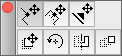
There are a number of options available should you need to adjust the marker in the plan view once it has been placed:
You can add nodes along the Elevation Line, where the offset from the source can be segmented and adjusted. Care should be taken should this option be chosen, that you don’t accidentally cut through parts of the building resulting in those parts displaying in section instead of elevation. Ensure you check that the segment locations work for all stories in your building.
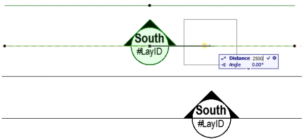
The Elevation line (i.e.. the position from where you are taking the view) can be moved either closer to the source or further away. This can also be used to adjust the position of any segment in step 1 above. Once again check on all stories before proceeding.
The Marker Head position can be adjusted along the line of the elevation in either direction. This is useful for readability to avoid clashes with other drawn elements on busy drawings.
The range of the marked distant area as well as the overall extent of the horizontal range can be adjusted. Select the node along the range line you wish to adjust, then simply move and place.
Setting up Views.
Follow the steps outlined in Views Set Up to save views of your Sections and Elevations.
Placing on Layouts.
Follow the steps outlined in Layout Book and View map to Layout Book to place these new Section and Elevation views on layouts
How to set up Sections.
Setting up sections is similar to setting up elevations, with the additional option that it have a zero depth, i.e. only show what is being cut through by the section line and nothing in the distance beyond that line.
Where to find: Toolbox or Document > Documenting Tools > Section
Use this to: Place a Section Marker.
As with Elevation Markers above, check the marker’s settings before you place it, and once again pay specific attention to the following:
General: Which type of marker you are placing and its subsequent Reference ID and Name.Again, as above, you would typically place a “Source Marker”.
Status: Manual Rebuild-model.
Range:
There are three options to choose from depending on your requirements:
Infinite.
The least used option for Sections as excessive distant information shown in your section can cause confusion and make drawings difficult to read.
Limited.
Used in a similar way to Elevations with a marked distant area. Useful for presentation and DA stages of a project.
Zero Depth.
This option is typically selected for construction documentation to prevent irrelevant distant information obscuring your drawing.
Marker:
Choose a marker object from the available libraries (in keeping with your office standards).
Select the Font type and size (in keeping with your office standards).
Set the size of the marker, and choose a Marker Style.
Set the various pen colours (in keeping with your office template).
As described above, the text which displays in the marker head (name and sheet number) is now set as follows:
Set Show Name to “On”, and both ID’s to “Off”. (You want the information in the Marker Head to be as simple and clear as possible).
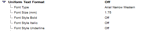
Set Uniform Text Format to “Off”. Once placed on your layout, the Sheet Number will display in the marker bubble. As this number can be quite long, you may want to reduce the text size, and unchecking will allow you to adjust this.
Marker Head:
Choose a Marker Style (in keeping with your office template).
Set the Pen Colour as well as Fill Type for the Marker.(Note that Fill Type is only applicable for some Marker styles.)
Also located here is a summary of the text settings for the First and Second Text Rows in your marker bubble. They can be set / edited here as well.
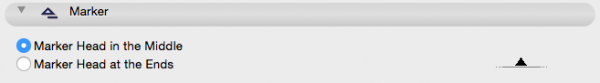
TIP > Typically, section lines show two marker heads, located at each end, The centre line segment is optional, typically used when the section line is staggered for clarity.
In this section you control how your model will be displayed. When you adjust Elevation Settings from design to construction stage, this section is where you would concentrate your efforts:
Cut Elements.
Adjust the way cut elements are displayed. For example, you can assign everything that is cut to use the same fill and the same pen. Useful if you want a more diagrammatic representation of your model. For example, for DA type drawings, set Cut Elements to Uniform Pen, and for Construction drawings, use “as in Settings” which will display the structure in the same way that the Plan view does..
Uncut Elements.
Adjust the way all uncut elements are displayed. For example if you want a very clean, line only drawing without colour, set the following options:
Fill Uncut Surfaces with > Uniform Pen Colour
Uncut Surfaces Pen > (-1) Window Background
Set Uncut Contours Pen as desired
Set Vectorial 3D Hatching as required
Un-tick Transparency so whatever is behind transparent element does not show.
Sun and Shadows.
The most consistent way is to leave this option on “Custom”. Even though this might not reflect reality, your drawing will read better graphically. You can also adjust the sun azimuth and altitude for each elevation, which is not an easy option if you choose to use “As in 3D Window”. Tick “Sun Shadow” to turn on the display of shadow, and choose the associated pen and fill type.
INFO > If you are using the Marked Distance Area as described next, you can override the pen and fill type for shadows for the distant range of the Elevation.
The pens and fills defined here will override the pens and fills that have been defined per drawn element, and will only be applied to the distant range of your elevation.
INFO > Within the horizontal range you can have two zones or ranges in your elevation to which you can assign separate model display settings.
For example, the range closest to the marker (foreground range) could be kept in colour, or even set to display the elements’ materials, and the pens for the range further away (distant range) can be overridden so that anything captured within that range displays in (for example) grey outline. This is an easy way to add graphical depth to your drawing.
The setting to turn this option on is in Elevation Default Settings > Model Display tab. Tick Marked Distance Area and adjust pens to suit. The two examples below show the effects obtained as a result of moving the line of Marked Distant Area.
Adjust the contours of elements at the extents of your elevation marker. For example, the ground mesh might extend beyond the extent of your elevation marker. (The ground mesh might be 100 meters wide and the elevation marker only 50 meters.) The settings here allow you to override what those lines at the extremities look like. Choose “No Contours” to indicate that the element continues beyond what is shown on the drawing.
Story Levels:
INFO > You can globally (!) turn on / off Story Level Lines and Story Markers by checking / unchecking the boxes in the Story Settings dialogue (COMMAND + 7).
TIP > Typically you would select one side only to display the story level markers. Select which is best graphically for your elevation, and provide an offset from the boundary (of the contained elevation) to ensure that the associated text does not interfere with the drawing.
Grid Tool:
This mainly defines whether you want to show or hide grid lines and their associated dimensions that you have drawn using the Grid Tool or Grid System.
TIP > To adjust the extent of your grid lines you will have to edit the individual grid line settings themselves, which will then be applied globally to all elevations and sections.
Check the option to Show Grid Elements.
Should the Grid lines be drawn in a Module file which is subsequently placed in your working file, choose “Selected” stories rather than “All” to avoid duplication of grid elements. Select the relevant story in the Select stories… tab.
Select “Show Grid Elements by Name”.
(You want all relevant grids displayed in your view).
Uncheck Dimension lines since these are typically only set out in your plan.
TIP > Save your settings as a favourite for use throughout your project. You can do this straight from the Default Settings dialogue > (Top left corner:) Favourites…
Select the appropriate layer on which to place your marker (e.g.. RefElev), then Go OK and proceed with placing the elevation marker on your drawing.
Adjusting the Section Marker.
Once again, similar to Elevations with the exception that due to there being a marker head on either end of the section line, these can not be moved to a suitable position for graphical clarity if need be. It is therefore important to place sections in your project in a suitable location early on in the documentation process, to avoid having them to move them later, as moving the location of line could potentially change the section entirely.
Setting up Views.
Follow the steps outlined in Views Set Up to save views of your Sections and Elevations.
Placing on Layouts.
Follow the steps outlined in Layout Book and View map to Layout Book to place these new Section and Elevation views on layouts.
macinteract Pty. Ltd. | ABN 44 155 154 653 | terms and legal. | © 2026
We use cookies to keep things running smoothly and help us improve—no secrets here!
Please select which cookies we can use. You can change your mind whenever you like!
Websites store cookies to enhance functionality and personalise your experience. You can manage your preferences, but blocking some cookies may impact site performance and services.
Essential cookies enable basic functions and are necessary for the proper function of the website.
These cookies are used for managing login functionality on this website.
Statistics cookies collect information anonymously. This information helps us understand how visitors use our website.
Google Analytics is a powerful tool that tracks and analyzes website traffic for informed marketing decisions.
Service URL: policies.google.com (opens in a new window)