


macinteract Pty. Ltd. | ABN 44 155 154 653 | terms and legal. | © 2026
How to Setup
Where to find: Toolbox or Document > Documenting Tools > Interior Elevation
Use this to: In the Construction Documentation stage of most projects, some spaces (e.g.. wet areas, kitchens, lobbies etc.) require additional information in order to accurately set out fittings and fixtures, joinery etc. As there are often standards and codes to which the heights of these fixtures and fittings must comply, internal elevation drawings are required in order to provide set-out dimensions. Other spaces (e.g.. lobbies, foyers etc.) may also require detailed set-outs in terms of joinery, cladding or wall finishes, and once again, internal elevation drawings are the most effective way of communicating this information to the builder.
2D versus 3D.
Depending on the size of your project, the level of modelling can vary greatly. In smaller projects you may well have used 3D objects for fixtures, fittings, joinery etc. You may also have used composite wall types which include finishes that have an associated vectorial hatch to represent, for example, wall tiling. This level of information makes the internal elevation process very quick and straightforward, usually only requiring additional notes, tags and dimensions.
However, in most cases the level of 3D information is not this extensive, and unless you have a good object library, a significant portion of your detailed internal elevations will need to be drawn in 2D. This may include 2D Library parts of fixtures and fittings (their elevational views), lines or fills representing joinery (e.g.. kitchen cabinetry), dimensions, annotation and tags. Additionally you may require fills, for example, to elevate and set out wall tiling.
Ideally, the minimum extent of 3D modelling should include floor slabs, ceilings, walls, doors and windows. Accuracy in modelling, as mentioned before, is crucial.
Placing the Internal Elevations Marker.
There are two main types of internal elevation markers:
1. Single, and
2. Multiple (including Polygonal, Rectangular & Rotated Rectangular).
These are typically used when only one wall of a space needs elevating. The Toolbox Settings Palette is divided into the same 6 panels as with Elevation and Section markers, namely:
Workflow:
General:
Select the “Single” Geometry Method and proceed to draw the marker.
Geometry Method: Single, Polygonal, Rectangular, Rotated Rectangular
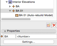
Select the marker group (!) in the Navigator and click Settings. (Selecting the Single Geometry Marker on plan and opening its settings does not provide you with the same options for naming!)
Set the Reference ID.
Although there are numerous linked options to choose from, unless you have used zones extensively throughout your project to define rooms/spaces and maintained those zones (which can be a very time consuming process in Construction Documentation), in which case you could select one of the Zone options, we recommend inserting custom text here (e.g.. the room name). The reason for this is that this text will primarily be used for listing purposes in your project map, and is not included in the text contained within the Marker Head.
Set the Name.
Since this will display in the Marker Head, use the Elevation Number option.
Set the Marker reference to “The first placed drawing of the viewpoint”. (Initially this will display as #LayID.) Once the internal elevation drawing has been placed on a sheet in your Layout Book, this will automatically substitute the sheet number in the marker head.
Select “Auto-rebuild Model” as the Status.
Ensure the Current Story is selected as Show on Stories.
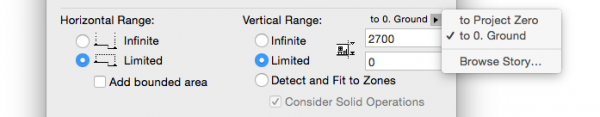
Set the Vertical Range.
Typically this will extend from the top surface of your floor finish to the underside of your ceiling. (This can be set to include floor- and ceiling finishes should this be a requirement of your project).
CAUTION > Check that the Vertical Range displays the correct story!
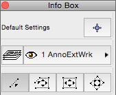
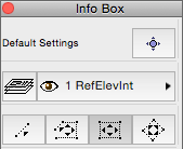
Marker:
Choose a marker object from the available libraries (in keeping with your office standards).
Set Marker Placement to be Individual for each Interior Elevation.
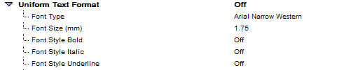
Select the Font type and size (in keeping with your office standards).
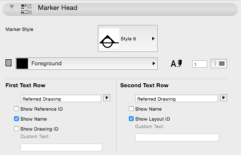
Set the size of the marker, and choose a Marker Style.
Set the various pen colours (in keeping with your office template).The text which displays in the marker head (name and sheet number) is now set as follows:
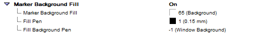
Set Show Name to “On”, and both ID’s to “Off”. (You want the information in the Marker Head to be as simple and clear as possible).
Set the Pen Colour as well as Fill Type for the Marker.
(Note that Fill Type is only applicable for some Marker styles.)
Also located here is a summary of the text settings for the First and Second Text Rows in your marker bubble. They can be set / edited here as well.
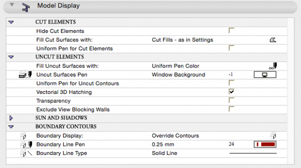
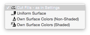
TIP > Generally you can ignore both “Own Surface Colours” options for Construction Documentation. They potentially have some use in presentation internal elevations but these are not common.
However, should you be elevating two adjacent spaces separated by a wall, for example adjacent bathrooms, and you wish to use one Internal Elevation drawing for both, select Hide Cut Elements, which will only display information on either side of the wall which will not appear. Or, alternatively, select Uniform Surface, which will display the shared wall as a grey fill.
In the Uncut Elements subsection, set Fill Uncut Surfaces with “Nothing” and otherwise check only the Vectorial 3D Hatching option.
Sun and Shadows should be turned off, i.e. unchecked.
Set Boundary Contours to either:
Uncut Contours (displays as a thin line), or
Override Contours, and select a thicker pen should you wish to draw a heavier outline around your internal elevation.
Story Levels:
Since it is uncommon to display story levels on internal elevation drawings, select “None”.
TIP > You could select “Display Only” option to aid with horizontal alignment on your Layout sheet. These levels will not print.
Grid Tool:
The size and complexity of your project will determine whether or not you should display Grid Lines on your internal elevations.
For example, a small residential project which has, say, only two bathrooms would not require grid lines in order to locate these areas, whereas a large scale multi residential development which has multiple lobbies, for example, needs to display grid lines to help assist with locating these on plan. Should you require grid lines, set them as described in the chapter on Elevations.
Select the appropriate layer on which to place your marker (e.g.. RefElevInt), then Go OK and proceed with placing the internal elevation marker on your drawing.
These are typically used when all the walls of a particular room or space need to be elevated.
In general follow all the settings as per Single Internal Elevations above, except for the following:
General:
Select the Geometry Method that is relevant to the shape of the space you want to make an Interior Elevation from.
In this example we’ll use the “Rectangular” Geometry Method.
Marker:
Set Marker Placement to be One common Marker for the IE Group.
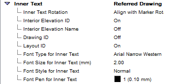
The Inner Text refers to the text contained within the Marker Head. The top line, i.e. the text above the dividing line is typically the room name (in this case, Bathroom or BT), and the bottom row is linked to the Layout sheet that your Internal Elevation group is placed on. Set Interior Elevation ID as well as Layout ID to “On”, and the rest to “Off”.
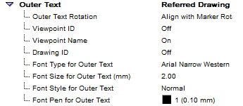
The Outer Text identifies the individual elevation numbers within your group, numbered in a clockwise direction starting at the top. Set Viewpoint Name to “On” and everything else to “Off”.
INFO > Uniform Text Format for this option is limited to the Inner and Outer Text. You are not able to differentiate between the size of the top and bottom text contained within the marker head.
Single Markers.
Workflow:
Select the appropriate layer combination, e.g.. Wet Area Enlarged S/E / Lift & Lobby Enlarged S/E etc.
Enlarge and set the drawing scale, typically Internal Elevations are drawn at 1:50, or more commonly, 1:20.
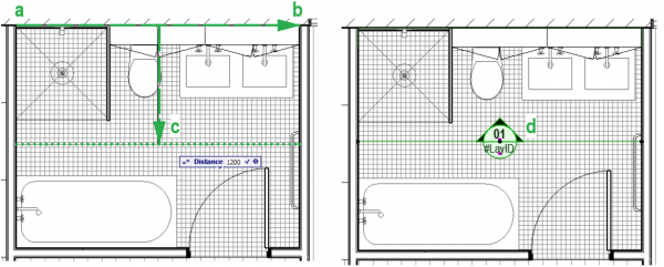
In your plan view,
Click on the endpoint of the wall you are elevating.
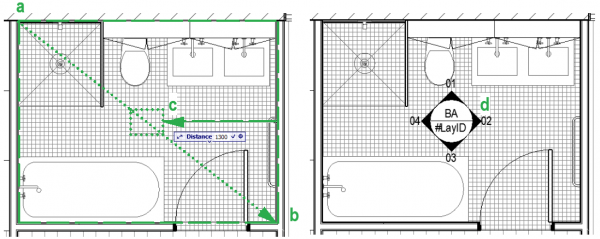
Hold SHIFT down (for orthogonal plans) and drag along the wall to the opposite endpoint, and click again. Note: Always check in the Tracker that the SHIFT constraint has picked up on the orthogonal and not an angle that is off! Using OPTION + a , x or y is a safer way to constrain dimensions.
Drag your mouse away a set distance, and
Click to place the marker head.
Workflow:
Follow the first 2 steps as per single markers above.
In your plan view,
Click on the first corner of the room you are elevating.
Drag your mouse diagonally to the opposite corner of the room, and click again.
Drag your mouse toward the middle of the space, and
Click to place the marker head.
TIP > Opposite to drawing a regular Elevation or Section Marker, where you start with the drawing the cutting or viewing position, with the Interior Elevation you start by drawing the limits of the elevation and only after that step place the Marker that defines your viewing position.
Using the Polygon Geometry Method does not make allowances for you to number the elevations in the Marker Head. We therefore recommend that when elevating more complex spaces (i.e.. not rectangular), use a number of single markers instead and number them as required.
Follow steps as described in the paragraph for Elevations.
Setting up Views.
Follow the steps outlined in Views Set Up to save views of your Sections and Elevations.
Placing on Layouts.
Follow the steps outlined in Layout Book and View map to Layout Book to place these new Section and Elevation views on layouts
Editing Fills.
Workflow:
Once your marker(s) has been placed, open the view via the Navigator Panel, or alternatively select the marker, right click and go Open Interior Elevation.
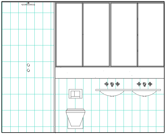
Initially, what will be displayed is dependent on the level of information you have modelled in 3D as explained earlier. For this example, we have made use of extensive 3D modelling, including vectorial hatching to represent wall tiles:
Now say for example, you have selected a building material for your walls which did not have an associated vectorial hatch, and as a result you need to use Fills to represent wall tiling:
Select the fill you wish to use, and draw it in the required locations in elevation view (of course ensuring correct pen colours, layers etc).
In our examples we have selected a contrasting Fill type to illustrate this.
INFO > Using Fills requires the Settings of the Interior Elevation Marker to be set to fill surfaces with “nothing” as outlined earlier. Drawn Fills will need to be Edit > Display Order > Send to Back and or trimmed around objects as described below.
By default, unless you specify an origin point and direction for your Fill, this set out point will be relative to the Project Origin (x=0; y=0):
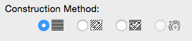
Since this is not ideal in terms of setting out tiles in the room you are drawing, before placing your Fill, select Relative to the Fill Origin as the Construction Method.
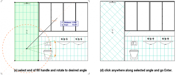
The origin (or Fill Handle) of the Fill is anchored by default at the centre of the fill area. From here the Set Out Point (SOP) as well as orientation of your tiling can be set. It is a simple process.
Although the Distorted Fill Construction Method has its uses, we do not recommend using this for tile set-out due to potential inaccuracies. Always use a fill where you have control over the dimensions representing the tiles.
TIP > Resetting the Construction Method of Fills can also occur after they have been drawn. Select the Fill, open its properties and proceed from there as outlined above.
CAUTION > Your Fill will need to be trimmed around objects in your elevation view in many cases, to avoid joint lines showing through other objects.
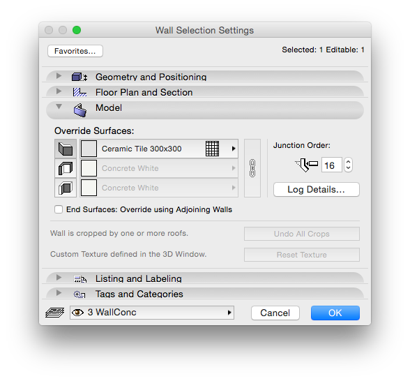
Since this can be tedious, consider instead using the Override Surfaces function for the elevated tiled wall, and selecting a surface with an associated vectorial hatch..
Adjust the set out point for the vectorial hatch in the 3D Window: Design > Align 3D Texture > Set Origin.
This can be tricky as you need to snap the cursor to your intended set out point, which might not be on an existing node of your wall surface.
If that is the case, then the quickest way is to draw a temporary wall so that one of its nodes is exactly there where the set out point should be. (e.g. if the set-out point is say 800 mm horizontally and 1200 mm vertically from a corner of the 3D element, then you would draw a wall alongside it with a length of 800 mm and height of 1200mm.) This way you can use that node in the 3D window to snap your cursor to when defining the texture’s origin.
INFO > Vectorial hatches only display if your 3D Window is set to Internal Engine!
macinteract Pty. Ltd. | ABN 44 155 154 653 | terms and legal. | © 2026
We use cookies to keep things running smoothly and help us improve—no secrets here!
Please select which cookies we can use. You can change your mind whenever you like!
Websites store cookies to enhance functionality and personalise your experience. You can manage your preferences, but blocking some cookies may impact site performance and services.
Essential cookies enable basic functions and are necessary for the proper function of the website.
These cookies are used for managing login functionality on this website.
Statistics cookies collect information anonymously. This information helps us understand how visitors use our website.
Google Analytics is a powerful tool that tracks and analyzes website traffic for informed marketing decisions.
Service URL: policies.google.com (opens in a new window)